4.2
cnci4
SUPERSET XL
OPERATING UNITS
4.1 TOOL ADJUSTMENT AND LOCKING ON SPINDLES
When the tools need adjustment, all the elements making up the tools must be dismantled and thoroughly cleaned
one by one with a harmless solvent, taking care not to confuse the elements between them in order to avoid
unbalancing. Remount the knives and the gibs and ensure that these do not protrude laterally from the planer body.
For the tools in contact with the shaving cutter see the NOTE. Also ensure that the knives are completely inserted
in the planer.
NOTE: With machines equipped with a shaver, take care that the planer knives intersect perfectly with the
shaver knives.
To set up the tools follow the instructions of the manufacture. For the traditional-type tools marked SCMI consult
paragraph 10.1.
The support surfaces of the tools must be perfectly clean. Locking and unlocking the fastening screws of the tool
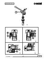
on the spindle is easily done with the wrench (A) supplied (see Fig. 4.1).
It is strictly inadvisable to disassemble and assemble a knife or parts of a tool if it is fixed to the spindle.
Warning!!! The tools must always be positioned on the spindle starting from the side near the bearing.
In the following paragraphs describing adjustment of the operating units reference is often made to the diameters
and positions of the tools. This page explains (fig. 4.2) what is meant by:
ØMAX = Maximum tool diameter
Ømin
= Minimum tool diameter
ØP
= Tool diameter under table (Adjustment or replacement of work table)
P
= Table in front of tool
B
= Distance between tool end-stop and table (vertical adjustment)
G
= Right guide
L
= Piece width (transversal adjustment of left vertical unit)
T
= Distance between tool end-stop and working height (transversal adjustment of spindle)
H
= Piece thickness (vertical adjustment of top horizontal unit)
(1) Right vertical unit, (2) Left vertical unit,
(3) Top horizontal unit, (4) 1st and 2nd bottom horizontal unit.
4
4
1
2
3
Summary of Contents for SUPERSET XL
Page 18: ...2 3 SUPERSET XL INSTALLATION cnusa2 max 90 1 2 0 0 m m 1 4 0 0 m m B C A P 2 1 ...
Page 20: ...2 5 SUPERSET XL INSTALLATION cnusa2 L2 L3 L1 PE Ref G 2 2 ...
Page 22: ...2 7 SUPERSET XL INSTALLATION cnusa2 2 3 L L2 N D C L2 L N D C ...
Page 24: ...2 9 SUPERSET XL INSTALLATION cnusa2 E 2 4 A 2 4a B ...
Page 26: ...2 11 SUPERSET XL INSTALLATION cnusa2 D E F A Q M CAUTION CAUTION CAUTION K H G S T U ...
Page 29: ...2 14 cnusa2 SUPERSET XL INSTALLATION ...
Page 48: ...4 7 SUPERSET XL cnci4 OPERATING UNITS H C 4 4 S V X G B 4 3 4 5 16 ...
Page 56: ...4 15 SUPERSET XL cnci4 OPERATING UNITS B 4 17 4 18 M C E D A Q Q 16 F ...
Page 58: ...4 17 SUPERSET XL cnci4 OPERATING UNITS 4 19 A B R P M C 4 19a 4 19b 4 19c M D E X ...
Page 60: ...4 19 SUPERSET XL cnci4 OPERATING UNITS 4 20 P M T G ...
Page 64: ...4 23 SUPERSET XL cncgb4_1 OPERATING UNITS S B Z C E E1 A M X R D E2 V K2 K1 J K1 ...
Page 66: ...4 25 SUPERSET XL cncgb4_1 OPERATING UNITS B Z C A M E R V K2 K1 G2 ...
Page 68: ...4 27 SUPERSET XL cncgb4_1 OPERATING UNITS E D D V K2 K1 G2 X1 W1 B Z C A M ...
Page 70: ...4 29 SUPERSET XL cncgb4_1 OPERATING UNITS B Z C A M D D K2 K1 G2 X1 W1 E E W1 V1 U P Y U ...
Page 73: ...4 32 cncgb4_1 SUPERSET XL OPERATING UNITS ...
Page 78: ...10 5 SUPERSET XL Cnusa10 ADJUSTMENT AND USE OF OPTIONAL UNITS B A P 10 3 ...
Page 82: ...10 9 SUPERSET XL Cnusa10 ADJUSTMENT AND USE OF OPTIONAL UNITS 10 7 10 8 N A V T R ...
Page 90: ...10 17 SUPERSET XL Cnusa10 ADJUSTMENT AND USE OF OPTIONAL UNITS 10 15 10 16 D B C E F G H L V ...
Page 98: ...10 25 SUPERSET XL Cnusa10 ADJUSTMENT AND USE OF OPTIONAL UNITS T P ...
Page 99: ...10 26 SUPERSET XL Cnusa10 ADJUSTMENT AND USE OF OPTIONAL UNITS ...
Page 102: ...19 3 SUPERSET XL Cnusa19 AUTO BRAKING MOTOR A B C ...
Page 104: ...19 5 SUPERSET XL Cnusa19 AUTO BRAKING MOTOR A B F C P D ...
Page 107: ...19 8 Cnusa19 SUPERSET XL AUTO BRAKING MOTOR ...
Page 110: ...20 3 SUPERSET XL MAINTENANCE Cnnci20 20 1 ...
Page 112: ...20 5 SUPERSET XL MAINTENANCE Cnnci20 R L S 20 2 20 3 V T 20 2a G ...
Page 114: ...20 7 SUPERSET XL MAINTENANCE Cnnci20 20 4 A M N K F 20 5 B 20 6 20 6a C M N ...
Page 116: ...20 9 SUPERSET XL MAINTENANCE Cnnci20 K F 20 7 20 7a 20 7b D E M N P Q R ...


