10.20
SUPERSET XL
Cnusa10
ADJUSTMENT AND USE OF OPTIONAL UNITS
ADJUSTMENTS (for machine with programmer)
To use the device in automatic mode, you must remove the left guide after the left vertical unit.
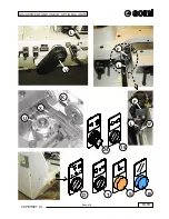
Limit switch (F) is designed to prevent the left vertical unit from colliding with other parts of the machine.
.
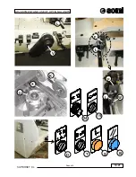
Adjustment of this device must be carried out with some care and depends on the position of the traction roller (K)
mounted in front of the left vertical unit, and on the tool diameter (U)
and, in versions with a grooved table (X), the type
of table fitted at the left vertical unit determines this adjustment.
Below follow the phases for proper adjustment:
a)
Mount the traction roller (K) of an adequate width for machining;
a1) if necessary, fit the appropriate worktable sector in front of the left vertical unit;
b) Mount the tool (U) required for machining on the left vertical unit;
c)
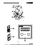
Turn the selector (24) to the position
, then turn the selector (T) to the position
Turn the selector (D) to the position "+" or "-" to bring the unit 3 ÷ 4 cm from the traction wheels.
d) Now turn the selector (T) to
, then turn the selector (16) to
to unlock the tool motor brakes;
e)
Act on the programmer (see programmer instructions) to draw the unit up to the maximum closing position,
then manually turn the tool spindle to check that there are no collisions.
f)
Now move the unit backward by about 10mm
from the traction wheel (K) or from the grooved table, if the
latter projects further than the traction wheel.
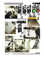
Loosen the screw (W), move the cam (L) until activating the limit switch housed in (F): this manoeuvre is carried
out checking that the yellow light (S) comes on. Retighten the screw (W).
g)
Turn the selector (16) to
and the selector (T) to
By acting on the selector (D) make the unit execute
a complete opening stroke and a complete closing stroke until the yellow light (S) comes on. With this
procedure the efficiency of the positioning motor brake is also checked.
h)
Turn the selector (16) to
to release the brakes, turn the tool spindle manually for the final check, and then
turn the selector (16) to
to relock the brakes.
i)
Check that the screw (W) is tightened and the cam (L) does not slide on the bar.
IMPORTANT!!! You must repeat this control every time you use the machine.
The device is now adjusted. Remount the spindle tool cover, close the horizontally-pivoted protection, set the selectors
(T) to
and (24) to
and start using the machine for production.
Warnings:
If the blue light (B) comes on, it indicates that a “RESET” cycle must be executed.
This occurs when:
- the machine is switched off and on again;
- passing from “Manual” mode
to “Automatic” mode
Unless the reset cycle is executed, the device cannot be used “in automatic”.
To execute the “RESET” cycle, the tool spindle motor must be switched off. Position the selector (T) to
and act
on the selector (D) to make the unit execute a complete opening and closing stroke until the yellow
light (S) comes on and the blue light (B) goes off.
Summary of Contents for SUPERSET XL
Page 18: ...2 3 SUPERSET XL INSTALLATION cnusa2 max 90 1 2 0 0 m m 1 4 0 0 m m B C A P 2 1 ...
Page 20: ...2 5 SUPERSET XL INSTALLATION cnusa2 L2 L3 L1 PE Ref G 2 2 ...
Page 22: ...2 7 SUPERSET XL INSTALLATION cnusa2 2 3 L L2 N D C L2 L N D C ...
Page 24: ...2 9 SUPERSET XL INSTALLATION cnusa2 E 2 4 A 2 4a B ...
Page 26: ...2 11 SUPERSET XL INSTALLATION cnusa2 D E F A Q M CAUTION CAUTION CAUTION K H G S T U ...
Page 29: ...2 14 cnusa2 SUPERSET XL INSTALLATION ...
Page 48: ...4 7 SUPERSET XL cnci4 OPERATING UNITS H C 4 4 S V X G B 4 3 4 5 16 ...
Page 56: ...4 15 SUPERSET XL cnci4 OPERATING UNITS B 4 17 4 18 M C E D A Q Q 16 F ...
Page 58: ...4 17 SUPERSET XL cnci4 OPERATING UNITS 4 19 A B R P M C 4 19a 4 19b 4 19c M D E X ...
Page 60: ...4 19 SUPERSET XL cnci4 OPERATING UNITS 4 20 P M T G ...
Page 64: ...4 23 SUPERSET XL cncgb4_1 OPERATING UNITS S B Z C E E1 A M X R D E2 V K2 K1 J K1 ...
Page 66: ...4 25 SUPERSET XL cncgb4_1 OPERATING UNITS B Z C A M E R V K2 K1 G2 ...
Page 68: ...4 27 SUPERSET XL cncgb4_1 OPERATING UNITS E D D V K2 K1 G2 X1 W1 B Z C A M ...
Page 70: ...4 29 SUPERSET XL cncgb4_1 OPERATING UNITS B Z C A M D D K2 K1 G2 X1 W1 E E W1 V1 U P Y U ...
Page 73: ...4 32 cncgb4_1 SUPERSET XL OPERATING UNITS ...
Page 78: ...10 5 SUPERSET XL Cnusa10 ADJUSTMENT AND USE OF OPTIONAL UNITS B A P 10 3 ...
Page 82: ...10 9 SUPERSET XL Cnusa10 ADJUSTMENT AND USE OF OPTIONAL UNITS 10 7 10 8 N A V T R ...
Page 90: ...10 17 SUPERSET XL Cnusa10 ADJUSTMENT AND USE OF OPTIONAL UNITS 10 15 10 16 D B C E F G H L V ...
Page 98: ...10 25 SUPERSET XL Cnusa10 ADJUSTMENT AND USE OF OPTIONAL UNITS T P ...
Page 99: ...10 26 SUPERSET XL Cnusa10 ADJUSTMENT AND USE OF OPTIONAL UNITS ...
Page 102: ...19 3 SUPERSET XL Cnusa19 AUTO BRAKING MOTOR A B C ...
Page 104: ...19 5 SUPERSET XL Cnusa19 AUTO BRAKING MOTOR A B F C P D ...
Page 107: ...19 8 Cnusa19 SUPERSET XL AUTO BRAKING MOTOR ...
Page 110: ...20 3 SUPERSET XL MAINTENANCE Cnnci20 20 1 ...
Page 112: ...20 5 SUPERSET XL MAINTENANCE Cnnci20 R L S 20 2 20 3 V T 20 2a G ...
Page 114: ...20 7 SUPERSET XL MAINTENANCE Cnnci20 20 4 A M N K F 20 5 B 20 6 20 6a C M N ...
Page 116: ...20 9 SUPERSET XL MAINTENANCE Cnnci20 K F 20 7 20 7a 20 7b D E M N P Q R ...


