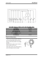
Connectors
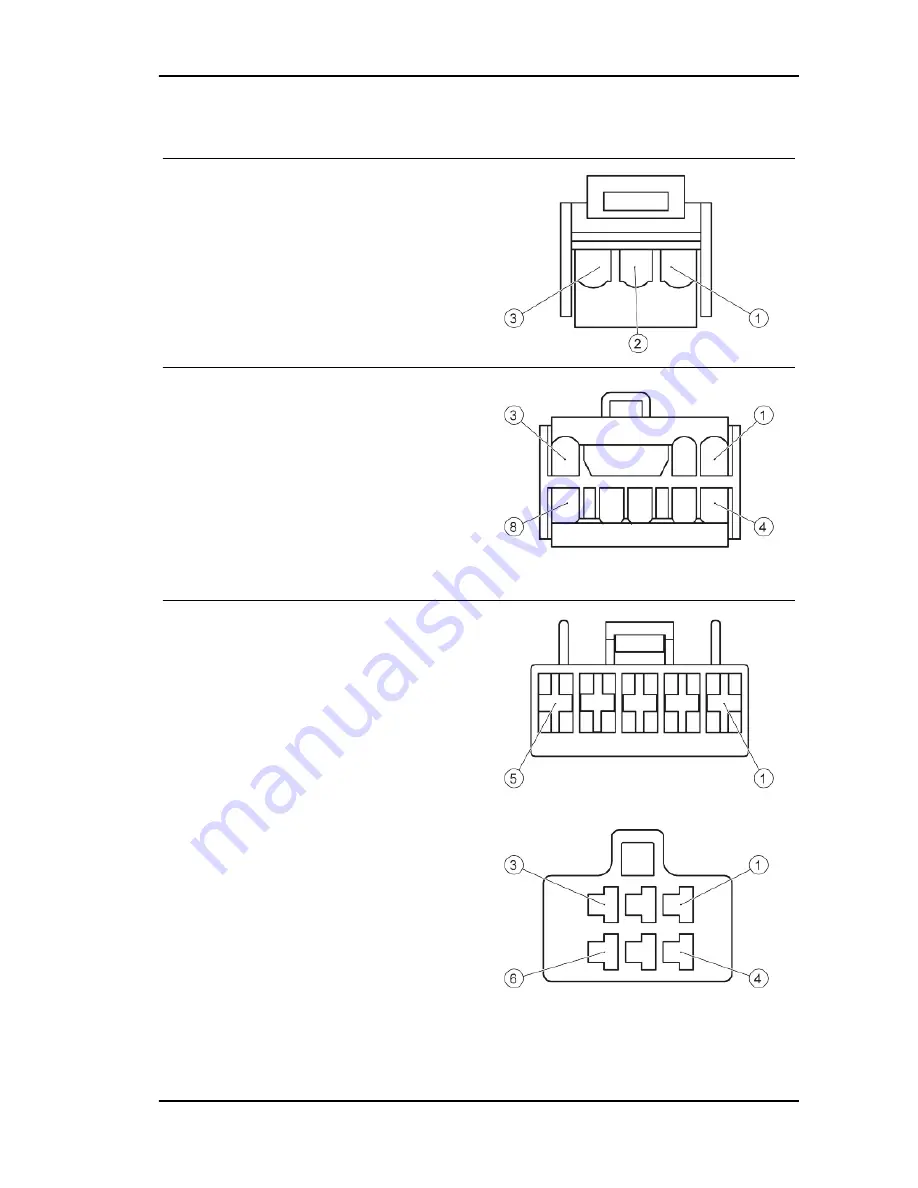
ELECTRONIC STARTER
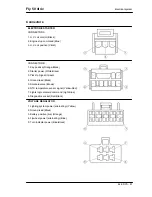
CONNECTOR A
1. H.V. coil control (Black):
2. Engine stop command (Blue)
3. H.V. coil positive (Violet)
CONNECTOR B
1. Key positive (Orange-Black)
2. Starter power (White-Black)
3. Pick-Up Signal (Green)
4. Ground lead (Black)
5. Solenoid valve (Brown)
6. NTC temperature sensor signal (Yellow-Red)
7. Lights logic solenoid command (Light Blue)
8. Diagnostics socket (Red-Black)
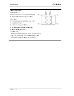
VOLTAGE REGULATOR
1. Lighting system power (alternating) (Yellow)
2. Ground lead (Black)
3. Battery positive (live) (Orange)
4. Flywheel power (alternating) (Blue)
5. Turn indicator power (Blue-Black)
Fly 50 4t 4v
Electrical system
ELE SYS - 91
Summary of Contents for Fly 50 4t 4v
Page 1: ...WORKSHOP MANUAL 677586 EN Fly 50 4t 4v ...
Page 4: ......
Page 6: ...INDEX OF TOPICS CHARACTERISTICS CHAR ...
Page 28: ...INDEX OF TOPICS TOOLING TOOL ...
Page 37: ...INDEX OF TOPICS MAINTENANCE MAIN ...
Page 49: ...INDEX OF TOPICS TROUBLESHOOTING TROUBL ...
Page 53: ...Fly 50 4t 4v Troubleshooting TROUBL 53 ...
Page 54: ...INDEX OF TOPICS ELECTRICAL SYSTEM ELE SYS ...
Page 63: ...7 Start up solenoid 8 At the battery connections Fly 50 4t 4v Electrical system ELE SYS 63 ...
Page 93: ...INDEX OF TOPICS ENGINE FROM VEHICLE ENG VE ...
Page 99: ...INDEX OF TOPICS ENGINE ENG ...
Page 158: ...INDEX OF TOPICS SUSPENSIONS SUSP ...
Page 173: ...INDEX OF TOPICS BRAKING SYSTEM BRAK SYS ...
Page 181: ...Fly 50 4t 4v Braking system BRAK SYS 181 ...
Page 182: ...INDEX OF TOPICS CHASSIS CHAS ...
Page 203: ...INDEX OF TOPICS PRE DELIVERY PRE DE ...
Page 208: ...V Vehicle 8 94 169 ...

