ScopeDome.com
2010 Slupsk - Poland
Electronics and driving systems fittings
F
G
A
C
H
D
B
I
J
Fig. 13 - Dome's driving motor system
scheme
A. Dome's side wall panel
B. Base ring
C. Cog-rim drive shield
D. Cog-wheel
E. Cog-rim
F. Motor ( engine)
G. Motor reductor (gear) (1/50)
H. Engine's mounting plate
I.
Driving ring
J. Driving ring bolt holes
C
D
E
F
A
B
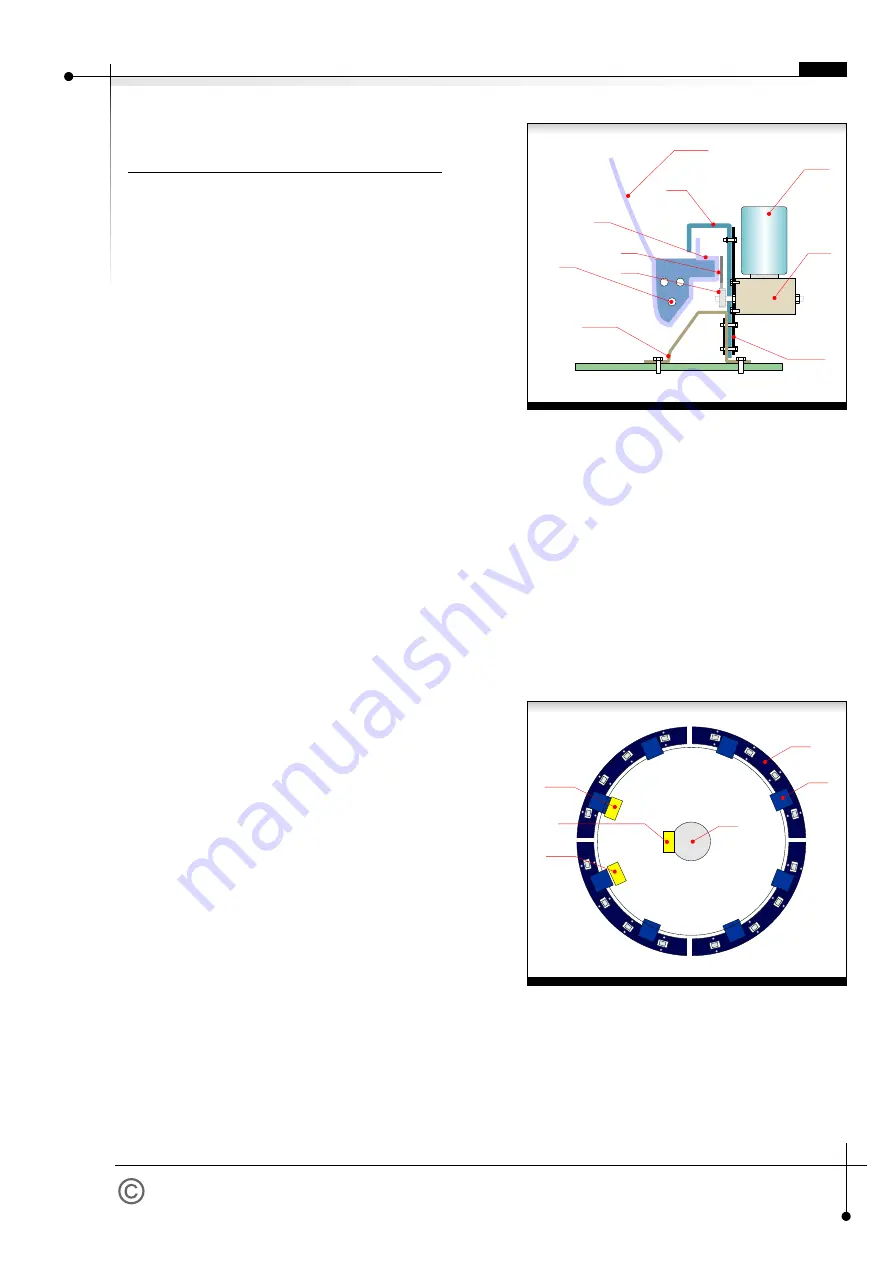
Fig.14 - Electrical installation diagram
A. Base ring
B. Cog-rim drive shield support/holder
C. Main power supply box
D. ScopeDome Card
E. Driving motor system with roller
F. Pier (a telescope basis)
page 8
E
Electronics and driving systems
fittings
Tip:
Tip:
-
Do not install shutter driving wire cables until you test
the shutter motor system end switches action and
the whole electronics.
-
Before you install the drivers and electrical
components, it is recommended to wash the dome
using a garden hose. Without this operation
removing the remains and debris will require much
more effort.
1. Fit encoder sensor (see fig 6). Start to rotate the
dome carefully, focusing your attention on possible
cog-rim abrasion. Encoder could be damaged very
easily if such abrasion appears.
2. Fit contactron "home" on drive shield.
3. Fit end switches on the front and the top of the
shutter window.
4. Fit the end switches pressing plate on the shutter in
a way that limit switches activate at about 2 cm
before full closing or full opening of the shutter.
5. Put contactron "home" magnet on the dome's back
at the distance from contactron "home" allowing
contactron's switches to be active as briefly during
the dome's rotation, as possible.
6. Stick encoder cleaning tape to cog-rim (see fig 10) at
contactron magnet (Home Sensor) height.
7. Fit the cable box on the rotary part of the dome.
8. Fit the ScopeDome Card on the one of the drive
shield or on scope's pier.
9. Fit the dome's driving motor on the drive shield
opposite to ScopeDome Card.
10. Connect all elements and wiring according to the
electrical diagram of the observatory.
11. Test driving motors and end switches.
12. Install control software and calibrate the dome.
(Calibration description in Help menu).
Limit switches control wiring and illumination wiring can
be lead through the holes previously drilled in the side
reinforcements close by shutter window.
EN


