Page 26
17.
If you are using keyed punches, manually rotate the punch so that the key seats in the ram before
tightening the nut.
18.
Tighten the punch retaining nut with a wrench. Make sure that there is equal clearance on all
sides of the punch in the die. NOTE: IF YOU ARE USING A HEAVY DUTY SPLIT-RING
RETAINING NUT, TIGHTEN THE BRASS BILLET SET SCREW AGAINST THE THREADS
OF THE RAM AFTER THE NUT HAS BEEN TIGHTENED.
19.
Re-tighten the bolts in the die holder.
20.
Check to be sure of proper alignment. Realign, if necessary.
21.
Return the stripper to the FORWARD position.
22.
Place the disconnect switch in the ON position and the selector switch in the START position.
Power the machine.
23.
Place the selector switch in the SHEAR position. To be sure that the clearance is correct, jog the
machine several times with the foot switch, without letting the punch come out of the die.
24.
Place the selector switch in the PUNCH position.
25.
Oil the punch and die before use and every 5 to 10 holes, thereafter.
(FOR LUBRICATION INSTRUCTIONS, SEE SECTION 5.1.)
26.
Punch three to five holes and re-tighten the punch retaining nut.
27.
The punch and die alignment should be checked intermittently during the punching operations.
To do this, bring the punch down so that it enters the die. Turn off the machine. Check and
tighten the punch retaining nut, the bolt holding the die, the two set screws holding the die insert
and the two bolts holding the die holder. Check for equal clearance between the punch and die.
Place the selector switch in the START position and power the machine. Place the selector switch
in the SHEAR position. Use the foot switch to jog the machine several times, to be sure of proper
alignment.
B.
CHECK ALL PUNCHING TOOLS FOR TIGHTNESS. Tools should be checked at the start of
each operation and intermittently during the work day. Check the punch retaining nut, die,
stripper and die holder. Tools tend to loosen under punching shock. Keep them tight to prevent
punch to die contact. NOTE: WHEN PUNCHING LARGE DIAMETER HOLES OR IN CASES
OF HIGH PUNCH SHOCK, IT WILL HELP IF THE STROKE OF THE MACHINE IS
ADJUSTED SO THAT THE PUNCH STOPS JUST ABOVE THE PLANE OF THE DIE.
C.
DO NOT PUNCH ANYTHING THICKER THAN THE PUNCH DIAMETER. This "rule of
thumb" can be extended, but the punch supplier or Scotchman should be consulted first. (i.e. Do
not punch plate thicker than 1/2 inch with a 1/2 inch diameter punch). This rule of thumb applies
to mild steel and must be reduced when punching alloy steels. Contact the factory or your local
dealer before attempting to punch any type of alloys.
D.
LUBRICATE THE PUNCH AND DIE. This will hold stripping forces to a minimum and greatly
extend punch life. Lubrication must be applied every 5 to 10 holes.
Summary of Contents for 9012-24M
Page 10: ...Page 9 FIGURE 1 ...
Page 12: ...Page 11 FIGURE 2 ...
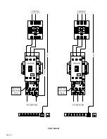
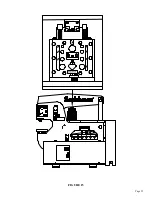
Page 16: ...Page 15 FIGURE 4A ...
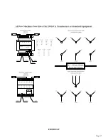
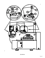
Page 17: ...Page 16 FIGURE 4B ...
Page 18: ...Page 17 FIGURE 4C ...
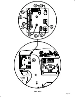
Page 22: ...Page 21 FIGURE 6 ...
Page 24: ...Page 23 FIGURE 7 ...
Page 35: ...Page 34 THIS PAGE LEFT BLANK INTENTIONALLY ...
Page 40: ...Page 39 FIGURE 15 ...
Page 42: ...Page 41 FIGURE 16 ...
Page 48: ...Page 47 FIGURE 20 ...
Page 54: ...Page 53 FIGURE 24 ...
Page 56: ...Page 55 FIGURE 25 ...
Page 62: ...Page 61 FIGURE 27 ...
Page 66: ...Page 65 FIGURE 29 ...
Page 68: ...Page 67 FIGURE 30 ...
Page 74: ...Page 73 FIGURE 32 ...
Page 78: ...Page 77 FIGURE 34 ...
Page 80: ...Page 79 FIGURE 35 ...
Page 82: ...Page 81 FIGURE 36 ...
Page 84: ...Page 83 FIGURE 37 ...
Page 86: ...Page 85 FIGURE 38 ...
Page 90: ...Page 89 FIGURE 41 ...
Page 92: ...Page 91 FIGURE 42 ...
Page 93: ...Page 92 FIGURE 43 ...
Page 96: ...Page 95 THIS PAGE LEFT BLANK INTENTIONALLY ...
Page 98: ...Page 97 FIGURE 46 ...
Page 100: ...Page 99 FIGURE 47 ...

