Page 66
7.15 MULTI-SHEAR TOOL
The Multi-Shear tool is designed to shear standard Unistrut profiles, as well as many other specialty
profiles.
7.15A MULTI-SHEAR TOOL INSTALLATION
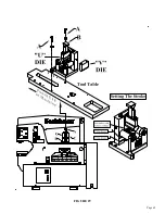
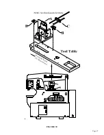
SEE FIGURE 30 ON THE FOLLOWING PAGE.
If the punch and die are mounted on the machine, REMOVE THEM.
1.
Turn the machine on and put it in the SHEAR position. Run the punch beam above the tool table
up to its highest setting.
2.
Place the tool on the tool table under the punch beam, keeping it towards the punch end of the
tool table.
3.
Use two finger clamps (B) and loosely mount the tool, using the 1st and fourth set of holes from the
left on the tool table, using one "front" hole and one "rear" hole, as shown.
DO NOT place the Multi-Shear tool any further towards the rear of the machine, due to possible
"bottoming out".
4.
Make sure that the tool is located under the beam correctly by aligning the pressure cap (A) under
the beam. Once the tool is squarely under the beam, tighten the finger clamps (B) to hold the tool in
place.
5.
Set the upstroke of the machine so that the size of material that you want to shear will feed through
the tool.
6.
Make sure that the upstroke is set so that there is spring tension on the pressure block at all times.
7.
Set the down stroke of the machine so that the moving blade travels only far enough to shear the
material and no further.
7.15B MULTI-SHEAR TOOL OPERATION
1.
The selector switch must be in the SHEAR position to operate this tool.
2.
Set the down stroke of the machine so that the moving blade travels only far enough to shear the
material and no further. "Bottoming out" this tool may ruin it!!
3.
Feed the material through the shear to the desired length and depress the foot pedal. Put the
Material Length Stop (C) screws into the back of the tool, if so desired.
4.
The pressure cap (A) has a grease zerk and the tool has two (2) grease zerks; one on each side.
Grease before using and every two hours thereafter.
5.
Lubricate the blades every ten to fifteen cuts.
CAUTION: ALWAYS REMOVE THIS TOOL WHEN IT IS NOT IN USE.
Summary of Contents for 9012-24M
Page 10: ...Page 9 FIGURE 1 ...
Page 12: ...Page 11 FIGURE 2 ...
Page 16: ...Page 15 FIGURE 4A ...
Page 17: ...Page 16 FIGURE 4B ...
Page 18: ...Page 17 FIGURE 4C ...
Page 22: ...Page 21 FIGURE 6 ...
Page 24: ...Page 23 FIGURE 7 ...
Page 35: ...Page 34 THIS PAGE LEFT BLANK INTENTIONALLY ...
Page 40: ...Page 39 FIGURE 15 ...
Page 42: ...Page 41 FIGURE 16 ...
Page 48: ...Page 47 FIGURE 20 ...
Page 54: ...Page 53 FIGURE 24 ...
Page 56: ...Page 55 FIGURE 25 ...
Page 62: ...Page 61 FIGURE 27 ...
Page 66: ...Page 65 FIGURE 29 ...
Page 68: ...Page 67 FIGURE 30 ...
Page 74: ...Page 73 FIGURE 32 ...
Page 78: ...Page 77 FIGURE 34 ...
Page 80: ...Page 79 FIGURE 35 ...
Page 82: ...Page 81 FIGURE 36 ...
Page 84: ...Page 83 FIGURE 37 ...
Page 86: ...Page 85 FIGURE 38 ...
Page 90: ...Page 89 FIGURE 41 ...
Page 92: ...Page 91 FIGURE 42 ...
Page 93: ...Page 92 FIGURE 43 ...
Page 96: ...Page 95 THIS PAGE LEFT BLANK INTENTIONALLY ...
Page 98: ...Page 97 FIGURE 46 ...
Page 100: ...Page 99 FIGURE 47 ...

