Page 98
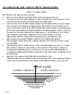
2° CANT
.035 (.030-.040)
.004 (.004-.008)
1/4
1/8
5/8
.75
1.0
1/2
3/8
MATERIAL THICKNESS
.022 (.018-.026)
.026 (.020-.030)
.017 (.012-.022)
.013 (.010-.017)
.009 (.007-.012)
BLADE CLEARANCE
DOUBLE CLEARANCE VALUE
FOR PUNCH AND DIE
CLEARANCE
(SERIAL #'S 21600 & PRIOR)
10.2 SHEAR BLADE ADJUSTMENT PROCEDURE
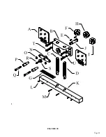
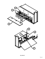
SEE FIGURE 47 ON THE FOLLOWING PAGE.
1.
Remove the shear table (K) and unlock the lock nuts on the back-up screws (E).
2.
Loosen the four (4) socket head retaining screws (D) that hold the lower blade support (C) to the
top of the shear bed and remove the blade and the lower blade holder.
3.
Lower the shear arm to the DOWN position. Replace the shear blade and the lower blade support.
Place a business card or shipping tag (approximately .010 in. thick) between the blades, one at
each end of the blades and one in the middle. Hold the blades firmly together and partially tighten
the (4) socket head retaining screws (D) that hold the lower blade support (C) in place. Adjust the
back-up screws (E) firmly against the lower blade support (C). (Do not tighten so as to compress
paper shims between the blades.) Tighten the (4) socket head retaining screws (D) to
approximately 100 ft.-lbs. torque and lock the back-up screws (E) with the lock nuts.
4.
Raise the shear arm and then LOWER IT SLOWLY, WATCHING THE BLADE
ENGAGEMENT. MAKE SURE THAT THE BLADES DO NOT COME IN CONTACT WITH
EACH OTHER.
5.
This adjustment will give a blade clearance of .005 to .010 thousandths of an inch (.12 to .25mm).
If the machine is being used to shear thicker sections of plate (1/2 inch (12mm) or thicker), we
recommend increasing the clearance. A clearance of 5 to 7 percent of the material thickness is
recommended. FOR RECOMMENDED CLEARANCES, SEE THE CHART AT THE BOTTOM
OF THIS PAGE.
6.
Replace the shear table (K). KEEP THE SHEAR SECTION CLEAR.
Small slivers, short cuts, etc. should be removed from the slug chute, to prevent build-up. Build-up
of short cuts can result in damage to the machine and POSSIBLE INJURY to other personnel.
Summary of Contents for 9012-24M
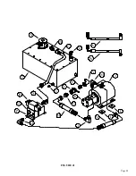
Page 10: ...Page 9 FIGURE 1 ...
Page 12: ...Page 11 FIGURE 2 ...
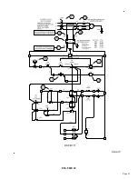
Page 16: ...Page 15 FIGURE 4A ...
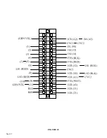
Page 17: ...Page 16 FIGURE 4B ...
Page 18: ...Page 17 FIGURE 4C ...
Page 22: ...Page 21 FIGURE 6 ...
Page 24: ...Page 23 FIGURE 7 ...
Page 35: ...Page 34 THIS PAGE LEFT BLANK INTENTIONALLY ...
Page 40: ...Page 39 FIGURE 15 ...
Page 42: ...Page 41 FIGURE 16 ...
Page 48: ...Page 47 FIGURE 20 ...
Page 54: ...Page 53 FIGURE 24 ...
Page 56: ...Page 55 FIGURE 25 ...
Page 62: ...Page 61 FIGURE 27 ...
Page 66: ...Page 65 FIGURE 29 ...
Page 68: ...Page 67 FIGURE 30 ...
Page 74: ...Page 73 FIGURE 32 ...
Page 78: ...Page 77 FIGURE 34 ...
Page 80: ...Page 79 FIGURE 35 ...
Page 82: ...Page 81 FIGURE 36 ...
Page 84: ...Page 83 FIGURE 37 ...
Page 86: ...Page 85 FIGURE 38 ...
Page 90: ...Page 89 FIGURE 41 ...
Page 92: ...Page 91 FIGURE 42 ...
Page 93: ...Page 92 FIGURE 43 ...
Page 96: ...Page 95 THIS PAGE LEFT BLANK INTENTIONALLY ...
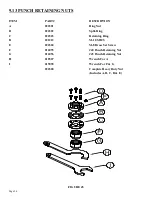
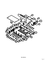
Page 98: ...Page 97 FIGURE 46 ...
Page 100: ...Page 99 FIGURE 47 ...


