PAGE 12
4.2 ASSEMBLING MACHINE & MOVING
ASSEMBLING OVERVIEW
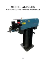
This grinder/notcher machine is shipped unassembled in a wooden crate.
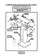
There are basically three (3) main parts. See FIGURE 3 on the next page.
FOOT PLATE: This is a 1 inch thick by 19-1/2 inch square metal plate that sits on the floor.
SUPPORT PILLAR: This is the rectangular "box" that mounts to the Base with 4 bolts and washers.
GRINDER: This is the main part of the machine. It mounts on top of the Column with
four (4) bolts and washers.
NOTE:
SEE FIGURE 3 ON THE NEXT PAGE
ASSEMBLY & MOVING MACHINE
• Remove loose components from the packaging. Inside the support pillar you will find a box with any
ordered grinding belts and grinding rollers, the grinding waste containers, the handle, and the
attachment hardware.
• Remove the attachment bolts with which the universal pipe notcher is attached to the bottom
plate of the packaging.
• Remove the wood screws with which the support pillar and foot plate are attached to the crate.
• Remove the support pillar from the packaging and bolt to foot with (4) bolts and washers.
• Remove the machine from the packaging. This part of the machine weighs approximately
225 kg (500 lbs) and keep in mind the "motor end" is the heaviest.
USING EXTREME CARE & THE PROPER LIFTING EQUIPMENT
Set it on top of the pillar as shown in FIGURE 3.
• Open the side cover of the machine and attach the machine to the support pillar using (4) M12 hex bolts
and nuts and (8) washers.
• Slide the grinding waste containers under the machine - One in front and the other in back.
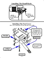
NOTE: Two (2) round aluminum hand-wheels need to be installed. FIGURE 4
However, an in-feed lever that can be mounted under the cross support is supplied with
this machine. The lever is used to feed the pipe into the belt for notching. The larger feed
handwheel and spindle must be removed for it to work.
It is used in conjunction with
the handwheel that moves the pipe side to side.
Summary of Contents for AL150-HS
Page 2: ...PAGE 2 MODEL AL150 HS HIGH SPEED PIPE NOTCHER GRINDER...
Page 11: ...6 2 3 5 7 8 FIGURE 2 4 1 PAGE 11...
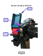
Page 19: ...PAGE 19 COVER SWITCH PLUNGER COVER SWITCH PUSHER HINGED COVER FIGURE 8 REAR COVER SWITCH...
Page 21: ...FIGURE 9 MODEL AL 150 HS 1 2 3 4 5 6 7 8 PAGE 21 9 ITEM 7 DETAIL CONTROLS ADJUSTMENTS...

