PAGE 14
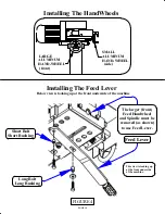
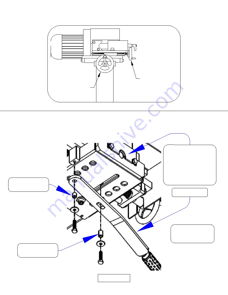
Installing The HandWheels
FIGURE 4
SMALL
ALUMINUM
HAND-WHEEL
(side)
LARGE
ALUMINUM
HAND-WHEEL
(front)
Installing The Feed Lever
Short Bolt
Short Bushing
Long Bolt
Long Bushing
This view is looking up
at the front underside
of the machine.
The larger (front)
Feed Handwheel
and Spindle must be
removed (as shown)
to use Feed Lever.
Feed Lever
Below view is looking up at the front underside of the machine
Summary of Contents for AL150-HS
Page 2: ...PAGE 2 MODEL AL150 HS HIGH SPEED PIPE NOTCHER GRINDER...
Page 11: ...6 2 3 5 7 8 FIGURE 2 4 1 PAGE 11...
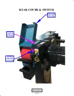
Page 19: ...PAGE 19 COVER SWITCH PLUNGER COVER SWITCH PUSHER HINGED COVER FIGURE 8 REAR COVER SWITCH...
Page 21: ...FIGURE 9 MODEL AL 150 HS 1 2 3 4 5 6 7 8 PAGE 21 9 ITEM 7 DETAIL CONTROLS ADJUSTMENTS...

