PAGE 16
4.5 WIRING DIAGRAMS
The wiring diagram for the AL 150 HS is on the next page - See FIGURE 6A.
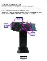
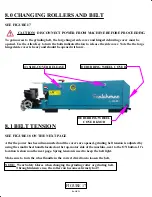
The wiring and electrical components are located on the motor side of the machine. To access the
electrical components, a cover needs to be removed (shown below).
The metal cover is mounted to the machine with six (6) bolts - Four (4) on the motor side and two
(2) on the deburring end of the machine. It fits around where the motor mounts.
ELECTRICAL
COVER
4
COVER
BOLTS
2
COVER
BOLTS
FIGURE 6
Summary of Contents for AL150-HS
Page 2: ...PAGE 2 MODEL AL150 HS HIGH SPEED PIPE NOTCHER GRINDER...
Page 11: ...6 2 3 5 7 8 FIGURE 2 4 1 PAGE 11...
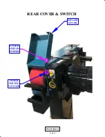
Page 19: ...PAGE 19 COVER SWITCH PLUNGER COVER SWITCH PUSHER HINGED COVER FIGURE 8 REAR COVER SWITCH...
Page 21: ...FIGURE 9 MODEL AL 150 HS 1 2 3 4 5 6 7 8 PAGE 21 9 ITEM 7 DETAIL CONTROLS ADJUSTMENTS...

