PAGE 20
MODEL - AL150-HS
REFER TO FIGURE 9
1.
Allen key, 8mm, with handle; for securing rotatable tubing clamp, for securing
standard stopper, and for adjustment of grinding belt.
2.
Allen bolts for opening and closing side cover. Use key with handle (1).
3.
Allen bolt to adjust belt tracking. Use key with handle (1).
4.
Hand Wheel for adjusting tubing clamp into and away from grinding roller.
5.
Hand Wheel for adjusting tubing clamp side to side to grinding roller.
6.
Handle for clamping work-piece in tubing clamp.
7.
Allen bolt for securing rotatable clamp. There is another bolt (not shown) in the center of the
clamp that also must be loosened & tightened to adjust the clamp. Use key with handle (1).
8.
Grinding Roller Support - Held in place by (2) wing-nuts.
9.
Hand Wheel used to adjust Grinding belt tension.
5.1 MACHINE CONTROLS & ADJUSTMENTS
Summary of Contents for AL150-HS
Page 2: ...PAGE 2 MODEL AL150 HS HIGH SPEED PIPE NOTCHER GRINDER...
Page 11: ...6 2 3 5 7 8 FIGURE 2 4 1 PAGE 11...
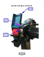
Page 19: ...PAGE 19 COVER SWITCH PLUNGER COVER SWITCH PUSHER HINGED COVER FIGURE 8 REAR COVER SWITCH...
Page 21: ...FIGURE 9 MODEL AL 150 HS 1 2 3 4 5 6 7 8 PAGE 21 9 ITEM 7 DETAIL CONTROLS ADJUSTMENTS...

