6.7 NOTCHING THE TUBING
SEE FIGURE 9
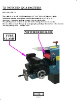
After adjusting to the correct angle (7) and the Stops (if desired) have been set up, clamp a piece of
tubing into the tubing clamp using the handle (6).
The side with hand wheel (5) moves tubing clamp side to side. It must be positioned so the piece of
tubing that is to be notched is moved toward the center of the grinding roller. Hand wheel (4) moves
tubing clamp into and away from the grinding roller. By moving the tubing clamp into the grinding
roller, the tubing section can be notched.
Care must be given to ensure that the width of the notch does not exceed the width of the grinding belt
on the roller. Otherwise, the tube would contact the roller itself. SEE FIGURE 16 - PAGE 30
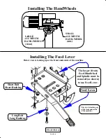
The Feed Lever (shown in SECT. 4.2, FIGURE 4) can be installed and used in conjunction with the
hand wheel (5). The larger hand wheel (4) and it's spindle must be removed to use the Feed Lever.
6.8 DEBURRING
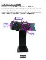
The other end of this machine is equipped with a deburring wheel for deburring the tubing that was
notched. There is a hinged cover that covers the deburring wheel that must be opened to access the
deburring wheel.
IMPORTANT: Go to SECTION 5 MACHINE START UP
and read the NOTE: and the CAUTION:
FOLD AWAY TOOL REST
The deburring end of the machine has a tool rest that is attached to the machine on the motor side. It
hangs below the machine when not in use.
THIS TOOL REST MUST BE USED FOR SAFETY!!!
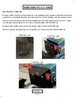
SEE FIGURE 12 and FIGURE 13
To use the Tool Rest - After the machine comes to a complete stop:
1.
Loosen tool rest mounting bolt with the 8mm Allen Key (See Figure 9 Item 1)
2.
Rotate the tool rest up toward and out from the deburring wheel
3.
There is a slot built into this end of the machine
4.
Tool Rest is made with a shaft that fits into this slot
5.
Insert the shaft into the slot and push the tool rest in toward the deburring wheel
6.
When the tool rest is 10mm (3/8") away from the deburring wheel, tighten the mounting bolt.
7.
When the machine is restarted, it will run in the opposite direction so deburring sparks are
directed downward into the grinding waste container located underneath the grinding wheel.
PAGE 25
Summary of Contents for AL150-HS
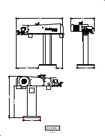
Page 2: ...PAGE 2 MODEL AL150 HS HIGH SPEED PIPE NOTCHER GRINDER...
Page 11: ...6 2 3 5 7 8 FIGURE 2 4 1 PAGE 11...
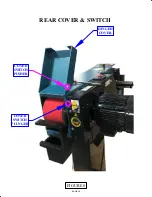
Page 19: ...PAGE 19 COVER SWITCH PLUNGER COVER SWITCH PUSHER HINGED COVER FIGURE 8 REAR COVER SWITCH...
Page 21: ...FIGURE 9 MODEL AL 150 HS 1 2 3 4 5 6 7 8 PAGE 21 9 ITEM 7 DETAIL CONTROLS ADJUSTMENTS...

