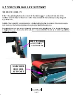
FIGURE 18
PAGE 32
8.2 NOTCHER ROLLER SUPPORT
SEE FIGURE 18 BELOW
Before the grinding belt can be removed, the roller support on the notcher end of the
machine must be loosened and one end of it disconnected. It is held in place by wing-nut
type fasteners.
NOTE: There should be a mark inside the grinding belt indicating the rotation. If not, make sure to
note which way the belt was turning so it can be reinstalled in the same way.
In most instances, the direction of rotation is indicated on the grinding belt. Even though this machine
is designed to reverse the rotation of the belt, it is recommended that the belt be installed to go with the
rotation for notching.
NOTCHER
ROLLER
SUPPORT
BELT TENSION
ADJUSTMENT
HANDWHEEL
Summary of Contents for AL150-HS
Page 2: ...PAGE 2 MODEL AL150 HS HIGH SPEED PIPE NOTCHER GRINDER...
Page 11: ...6 2 3 5 7 8 FIGURE 2 4 1 PAGE 11...
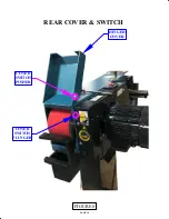
Page 19: ...PAGE 19 COVER SWITCH PLUNGER COVER SWITCH PUSHER HINGED COVER FIGURE 8 REAR COVER SWITCH...
Page 21: ...FIGURE 9 MODEL AL 150 HS 1 2 3 4 5 6 7 8 PAGE 21 9 ITEM 7 DETAIL CONTROLS ADJUSTMENTS...


