background image

31

8.3

Setting Belt Tension

33

8.1

Belt Tension 

31

8.2

Notcher Roller Support

32

CHANGING ROLLERS AND BELT

8.0 

40

8.5

Adjustment Of Grinding Roller

36

8.4

Setting The Belt Tracking

35

37

38

38

40

41

AVAILABLE OPTIONS

9.0 

9.1

Roller Holder

AVAILABLE ROLLERS

10.0 

45

AVAILABLE GRINDING BELTS

11.0 

AL 150-HS PARTS LIST

12.0 

AL 150-HS Exploded Views 

SCOTCHMAN INDS. - 180 E US HWY 14 - PO BOX 850 - PHILIP, SD 57567  Call:  1-605-859-2542

Changing The Roller

8.6

12.1

49

OPTIONAL BACK GAUGE

PAGE 5

Summary of Contents for AL150-HS

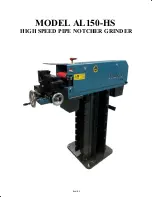
Page 1: ...www scotchman com MODEL AL150 HS HIGH SPEED PIPE NOTCHER GRINDER VERSION 1 JULY 2019 SCOTCHMAN INDS 180 E US HWY 14 PO BOX 850 PHILIP SD 57567 Call 1 605 859 2542...

Page 2: ...PAGE 2 MODEL AL150 HS HIGH SPEED PIPE NOTCHER GRINDER...

Page 3: ...e to the higher grinding belt speed of 4 300 RPM Also your grinding belt will see a 3 times longer life than other grinders when grinding at this High Speed This machine will grind steel stainless ste...

Page 4: ...Moving 10 4 3 4 4 16 4 5 Wiring Diagrams 15 18 15 5 1 Machine Controls Adjustments 22 22 6 2 Drive for the Grinding Belt 23 6 3 Securing a Tubing Section 24 6 4 Angle Adjustment 25 6 1 Starting and S...

Page 5: ...Roller 36 8 4 Setting The Belt Tracking 35 37 38 38 40 41 AVAILABLE OPTIONS 9 0 9 1 Roller Holder AVAILABLE ROLLERS 10 0 45 AVAILABLE GRINDING BELTS 11 0 AL 150 HS PARTS LIST 12 0 AL 150 HS Exploded V...

Page 6: ...nd well trained in the operation of the machine The operators must be aware of the capacities of the machine and the proper use of the holding device and the guards provided with the machine This manu...

Page 7: ...fective goods freight and delivery prepaid to the seller which shall be the buyer s sole and exclusive remedy for defective goods Hydraulic and electrical components are subject to their respective ma...

Page 8: ...Sticker 8 x 8 cm 2 1 A050 00025 Sticker side flap 13x5 cm 3 1 A050 00045 Instruction sticker AL150HS 4 1 N A Triangle Pinch Point Sticker Item 3 0 MACHINE DECALS 2 4 3 1 CE Identification on Other Sid...

Page 9: ...ECTION REQUIRED PICTOGRAM 3 USE OF HEARING PROTECTION REQUIRED PICTOGRAM 4 KEEP LID CLAP CLOSED WHILE BELT IS IN MOTION BEFORE OPERATING THIS MACHINE Strictly comply with all warning labels and decals...

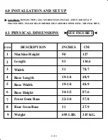
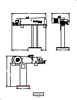
Page 10: ...AD THOROUGHLY BEFORE OPERATING THIS MACHINE 4 1 PHYSICAL DIMENSIONS SEE FIGURE 2 1 Machine Height 50 127 2 53 134 6 3 4 5 6 7 8 9 31 78 7 34 1 2 87 6 22 3 4 57 8 Length 11 27 9 Width Front from Base 6...

Page 11: ...6 2 3 5 7 8 FIGURE 2 4 1 PAGE 11...

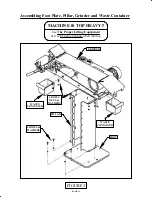
Page 12: ...ottom plate of the packaging Remove the wood screws with which the support pillar and foot plate are attached to the crate Remove the support pillar from the packaging and bolt to foot with 4 bolts an...

Page 13: ...IS TOP HEAVY Use The Proper Lifting Equipment Use Extreme Caution when moving Assembling Foot Plate Pillar Grinder and Waste Container GRINDER PILLAR FOOT WASTE CONTAINER WASTE CONTAINER 4 BOLTS NUTS...

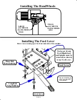
Page 14: ...ront Installing The Feed Lever Short Bolt Short Bushing Long Bolt Long Bushing This view is looking up at the front underside of the machine The larger front Feed Handwheel and Spindle must be removed...

Page 15: ...ltage should be 10 of the motor voltage rating Check the motor data tag for full load current requirements The electrical diagram for the motor is inside the cover of the motor box For electrical supp...

Page 16: ...located on the motor side of the machine To access the electrical components a cover needs to be removed shown below The metal cover is mounted to the machine with six 6 bolts Four 4 on the motor sid...

Page 17: ...V50 60Hz 1 L1 3 L2 5 L3 2 T1 4 T2 6 T3 13 A 1 NO 14 A 2 NO XTCE012B10 230V50 60Hz 1 L1 3 L2 5 L3 2 T1 4 T2 6 T3 INCOMING LINE POWER 4 3 NO 4 3 NO 2 1 NC BN BK BU BKWH 4 0 96 95 98 97 N C N O 2 0 8 0 1...

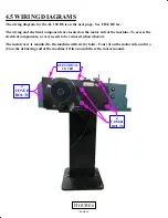
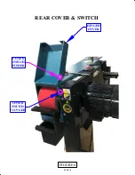
Page 18: ...fter a pipe has been notched in order to deburr it on the other end of the machine the grinding belt must change directions REFER TO FIGURE 8 ON THE NEXT PAGE A switch is mounted on the deburring end...

Page 19: ...PAGE 19 COVER SWITCH PLUNGER COVER SWITCH PUSHER HINGED COVER FIGURE 8 REAR COVER SWITCH...

Page 20: ...Wheel for adjusting tubing clamp into and away from grinding roller 5 Hand Wheel for adjusting tubing clamp side to side to grinding roller 6 Handle for clamping work piece in tubing clamp 7 Allen bo...

Page 21: ...FIGURE 9 MODEL AL 150 HS 1 2 3 4 5 6 7 8 PAGE 21 9 ITEM 7 DETAIL CONTROLS ADJUSTMENTS...


Page 22: ...n the grinding belt Even though this machine is designed to reverse the rotation of the belt it is recommended that the belt be installed to go with the rotation for notching 6 3 SECURING A TUBING SEC...

Page 23: ...th an Allen bolt and the 8mm Allen key can be used for adjustment The Depth Stop is designed to ensure that a series of tubing sections with the same dimensions are all notched to the same depth FIGUR...

Page 24: ...bing is clamped in the tubing clamp the same A Length Stop used in conjunction with the Depth Stop will make for grinding an easily repeatable and very consistent notch into the same sized tubing Agai...

Page 25: ...deburring wheel for deburring the tubing that was notched There is a hinged cover that covers the deburring wheel that must be opened to access the deburring wheel IMPORTANT Go to SECTION 5 MACHINE ST...

Page 26: ...SEE FIGURE 12 Below SEE FIGURE 13 on the Next Page FIGURE 12 TOOL REST IMAGES TOOL REST POSITION WHEN NOTCHING TOOL REST MOUNTING BOLT SLOT IN MACHINE SHAFT ON TOOL REST PAGE 26...

Page 27: ...FIGURE 13 TOOL REST IS 3 8 AWAY FROM GRINDING WHEEL MOUNTING BOLT below IS TIGHT READY FOR USE PAGE 27...

Page 28: ...of the machine is used This cover is stored on the motor side of the machine below the motor and electrical cover It is hung on to the pillar and just lift up on it to remove it from the pillar SEE F...

Page 29: ...nd 2 pipe mandrels 1 1 4 1 1 2 There are 17 mandrels available to ensure correct gap free fits The grinding rollers mandrels and belt can be changed tool free in seconds The size of the notch is chang...

Page 30: ...es for the AL 150 Grinder Notchers when grinding tubes at an angle The tube size must be reduced as the angle is increased ANGLE RANGE STRAIGHT 90 TO 20 90 60 45 30 20 Max 1 7 8 48 3mm Max 3 48 3mm Ma...

Page 31: ...L COVER FIGURE 17 8 1 BELT TENSION SEE FIGURE 18 ON THE NEXT PAGE After the power has been disconnected and the covers are opened grinding belt tension is adjusted by using the small wheel handle loca...

Page 32: ...There should be a mark inside the grinding belt indicating the rotation If not make sure to note which way the belt was turning so it can be reinstalled in the same way In most instances the direction...

Page 33: ...REMELY HOT Below are a couple of images that show how the roller mounts to the machine Each roller has 2 bearings One on each end The roller is held in the holder with 2 spring pressure retainers Thes...

Page 34: ...f the support for the grinding roller must be cleaned thoroughly NOTE The bearings that are mounted on the grinding roller must be handled with care because they can be easily damaged Make sure they a...

Page 35: ...ew grinding belt is very stiff and may break if used on a grinding roller with a small diameter After installing the new grinding belt the notcher roller support must be reattached via the 2 wing nut...

Page 36: ...pped down deburring cover is closed Connect the power to the machine NOTE Make sure you are wearing the proper safety equipment At this point we re ready to start the machine Be prepared to stop the m...

Page 37: ...of the tubing This is set at the factory and generally doesn t need to be adjusted If the center of the tubing isn t centered on the grinding roller it can be adjusted with the 2 bolts that are aligne...

Page 38: ...al 15 rollers This is a sheetmetal part that attaches to the front of the machine There are 2 slots in the front on the column of the AL150 HS and the Roller Holder has 2 angled tabs that fit thru the...

Page 39: ...COLUMN ROLLER HOLDER INSTALLATION ENLARGED ISOMETRIC VIEW EXTRA ROLLERS ARE STORED SECURELY IN CUT OUTS ROLLER HOLDER FIGURE 25 PAGE 39...

Page 40: ...Belts A044 00002 Item Length Grit Part number Packaging 6 x 78 3 4 36 1 box 10 belts A044 00004 6 x 77 1 2 36 1 box 10 belts PIPE PART NUMBER 1 2 A043 21 3 3 4 A043 26 9 1 A043 33 7 1 1 4 A043 42 4 1...

Page 41: ...1 04 00842 Turning Part Big Washer 1 04 00840 Eccentric 1 E030 00019 Motor 230 400V 50Hz 3F 4KW 1 04 00825 Pulley 40T10 36 1 04 00871 Timing Belt 25T10 630 1 04 00858 Plate 4 G020 00013 SKF Bearing 6...

Page 42: ...x190 Bzk ck schr M10x190 57 6 01300 M10 Zk nut M10 58 4 01200 M12x40 01200 M12x40 49 6 01300 M12 Zk nut M12 50 2 38130 M16 Vlk sluitr M16 51 7 07840 M5x6 Bzk st schr M5x6 45H ke 52 1 01210 M8x100 Sock...

Page 43: ...chr M6x30 45H ke 76 2 37963 M6 Locking gr M6 DIN 25 201 77 2 01300 M6 Zk Nut M6 78 1 07160 M6x12 Bzk ck schr M6x12 79 2 07160 M6x12 Bzk ck schr M6x12 80 1 38400 M6x30 Body Ring M6x30 81 1 38400 M6x20...

Page 44: ...110 04 00879 Ash 111 04 00185 Pipe 112 04 00885 Anti Vibration strip 113 2 01210 M6x16 Socket Screw M6x16 114 1 M130 00003 Allen Key 115 1 A050 00046 Easy Grinding Power Sticker 116 1 A050 00003 Almi...

Page 45: ...41 85 68 80 64 63 75 38 78 77 32 60 10 46 58 29 116 112 27 55 54 57 83 58 28 37 65 36 113 121 4 43 69 56 2 1 SCOTCHMAN INDS 180 E US HWY 14 PO BOX 850 PHILIP SD 57567 Call 1 605 859 2542 PAGE 45 12 1...

Page 46: ...0 47 12 59 25 124 5 7 8 44 22 82 23 11 48 21 31 26 52 17 61 20 39 30 24 51 24 21 16 15 33 49 6 42 19 18 MOTOR WITH MOUNTING PLATE PULLEY PAGE 46 SCOTCHMAN INDS 180 E US HWY 14 PO BOX 850 PHILIP SD 575...

Page 47: ...111 117 3 40 79 77 78 62 120 118 123 66 53 45 9 32 60 60 63 PAGE 47 SCOTCHMAN INDS 180 E US HWY 14 PO BOX 850 PHILIP SD 57567 Call 1 605 859 2542...

Page 48: ...4 109 106 110 108 100 104 102 103 105 98 73 60 94 93 89 90 70 71 50 88 74 70 92 55 91 59 81 95 56 72 99 96 92 50 101 97 PAGE 48 SCOTCHMAN INDS 180 E US HWY 14 PO BOX 850 PHILIP SD 57567 Call 1 605 859...

Page 49: ...chines It mounts to the side of the tube clamp and is a real Time Saver when you have many pieces of tubing that are the same length that need to be notched Contact your Dealer or call us at 1 605 859...

Reviews: