DWN. BY:
CHK. BY:
Scotchman Inds.
PART NO.
.0 = +/-.02 (.5mm)
.00 = +/-.01 (.25mm)
.000 = +/-.005 (.125mm)
Fractions = +/- 1/32 (.7mm)
Angles = +/- 1'
DATE:
SCALE:
PART NAME:
MATERIAL:
TOLERANCE (UNLESS SPECIFIED)
5/12/16
Jason S.
None
Cold Saw Blade
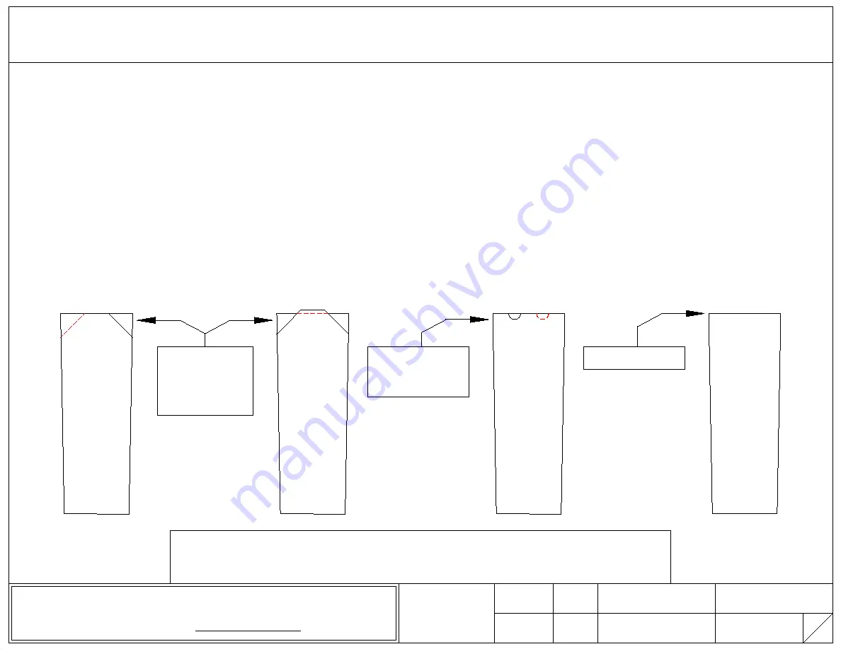
Selecting the Proper
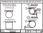
ALTERNATE
Teeth are the same Height.
All the Teeth have a Bevel.
Every Other Tooth is Beveled
on Every Other Side. Used on
Blades with a 4.5 Pitch or Less,
Generally, 220 Teeth or more.
More Teeth = Smaller Pitch
Used on thinner walled Tube &
Angle and Small Solids.
TRIPLE CHIP
Every other Tooth is Taller.
Often said to have a "High-Low".
The High-Tooth has a Bevel on Both
Sides. The Low Tooth has
NO Bevel at all. Hi-Tooth cuts the
Middle out of the Cut and Low
Tooth is the Tooth that leaves Finish.
Generally used on Blades
with a 4.5 Pitch or more.
Less Teeth = Larger Pitch.
Best for Solids and Thick Wall Tube.
NOTCH GRIND
Teeth are the same Height.
All the Teeth have a Notch.
Notches are Offset from Each
Other and breaks up the Chip
made during the Cut. Typically
used on Blades with a 4.5 Pitch or
Less, Generally, 220 Teeth or more.
More Teeth = Smaller Pitch
Best for thinner walled Tube &
Blade RPM should be increased.
ROUND GRIND
Teeth are the same Height.
There is No Bevel. Typically used
on Blades with a 3.5 Pitch or Less,
as Teeth this small are extremely
difficult to bevel. This works best
for thinner walled Tube .
Also used for soft materials such as
Nylon, Plastic, PVC, etc. in most
any shape or size and with
whatever tooth size works the best.
Bevel at 45° Angle
Removes 1/3 of the
"Tip of the Tooth"
Where the cutting
takes place.
3
3
Notches are Off-Set
Breaks up the chip
made during the cut
No Bevel or Notch
TYPES OF BEVELS, NOTCHES, AND WHERE USED
Power 2000 Blades have the Notch Grind & Titanium Coating.
Triple Chip and Alternate Grinds are by far the most common.
The Worlds Best Cold Saws & Ironworkers
Proudly Made In America
www.scotchman.com
Scotchman Inds.
180 E US Hwy 14
Philip, SD 57567
1-605-859-2542
info@scotchman.com
Summary of Contents for CPO-275
Page 8: ...Page 7 FIGURE 1...
Page 10: ...Page 9 FIGURE 2...
Page 13: ...Page 12 MANUAL OR PK W TRIGGER SWITCH FIGURE 3 1...
Page 14: ...Page 13 PKPD W EMERGENCY STOP FIGURE 3 2...
Page 15: ...Page 14 1 PHASE MOTOR W TRIGGER SWITCH FIGURE 3 3...
Page 16: ...Page 15 1 PHASE MOTOR W E STOP SERIAL S B3431 UP FIGURE 3 4...
Page 22: ...Page 21 FIGURE 5A...
Page 28: ...Page 27 FIGURE 8 FIGURE 9...
Page 30: ...Page 29 FIGURE 10...
Page 36: ...FIGURE 14 Page 35 C A B D...
Page 38: ...Page 37 FIGURE 15...
Page 40: ...Page 39 FIGURE 16...
Page 42: ...Page 41 FIGURE 17...
Page 44: ...Page 43 FIGURE 18...
Page 46: ...Page 45 FIGURE 19...
Page 48: ...Page 47 FIGURE 20...
Page 50: ...Page 49 FIGURE 20A...
Page 58: ...Page 57 FIGURE 23...
Page 60: ...FIGURE 24 Page 59...
Page 62: ...Page 61 G 078000 60 RPM 230 Volt 1 Phase T S 078001 60 RPM 230 Volt 1 Phase E S FIGURE 25...
Page 66: ...Page 65 FIGURE 27...
Page 68: ...Page 67 FIGURE 28...
Page 70: ...Page 69 FIGURE 29...
Page 74: ...Page 73 FIGURE 31...
Page 76: ...Page 75 FIGURE 32...
Page 78: ...Page 77 FIGURE 33...
Page 80: ...FIGURE 34 Page 79...
Page 82: ...Page 81 FIGURE 35...
Page 84: ...Page 83 FIGURE 36...
Page 86: ...Page 85 FIGURE 37...
Page 88: ...Page 87 FIGURE 38...
Page 90: ...Page 89 FIGURE 39...

