5.2 CUTTING OILS AND LUBRICANTS
5.3 SCHEDULED MAINTENANCE
A program of scheduled maintenance should be set up and documented according to your application
and the frequency with which you use this machine. The following is a list of some important things that
should be included in a scheduled maintenance program.
1. EVERY 250 HOURS OR 3 MONTHS:
Drain the coolant reservoir and flush it out. Refill the coolant reservoir with new coolant.
This will extend the life of the coolant pump considerably.
2. EVERY 500 HOURS OR 6 MONTHS:
Drain the gear oil from the saw head and flush with a petroleum product. Refill the saw head
with Mobil 600W Super Cylinder Oil. Check the condition of the pivot pins on the head and
Check the complete saw for loose connections in the electrical and air systems. If your saw is
equipped with the power vise or power down feed options, SEE SECTIONS 7.1 THRU 7.2, for
additional information. Since every application is different, each user must design and implement
a scheduled maintenance program that fits his applications.
Page 19
on the guard.
SECTION 10.5 lists Scotchman’s parts numbers for cutting oils and lubricants. Using high quality
lubricants and oils will greatly increase the life of this equipment. We recommend using only pure,
synthetic, water soluble cutting oil for coolant. For the saw head, use a non-EP additive ISO-460 gear
oil specified for worm gears. Oils containing EP additives may degrade or damage bronze gears and
must be avoided. Mobile 600WSuper Cylinder Oil is highly recommended and available from the
factory under P/N 075758.
On saws equipped with the power down feed, use SAE 10W (ISO 32) non-foaming hydraulic oil, such
as Mobil DTE 10 or equivalent. On saws equipped with air lubricators, use a high quality (ISO 22) air
line lubricant designed for automatic oilers.
Summary of Contents for CPO-275
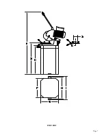
Page 8: ...Page 7 FIGURE 1...
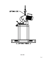
Page 10: ...Page 9 FIGURE 2...
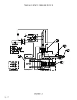
Page 13: ...Page 12 MANUAL OR PK W TRIGGER SWITCH FIGURE 3 1...
Page 14: ...Page 13 PKPD W EMERGENCY STOP FIGURE 3 2...
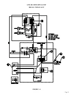
Page 15: ...Page 14 1 PHASE MOTOR W TRIGGER SWITCH FIGURE 3 3...
Page 16: ...Page 15 1 PHASE MOTOR W E STOP SERIAL S B3431 UP FIGURE 3 4...
Page 22: ...Page 21 FIGURE 5A...
Page 28: ...Page 27 FIGURE 8 FIGURE 9...
Page 30: ...Page 29 FIGURE 10...
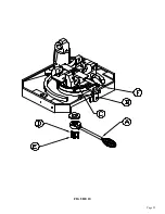
Page 36: ...FIGURE 14 Page 35 C A B D...
Page 38: ...Page 37 FIGURE 15...
Page 40: ...Page 39 FIGURE 16...
Page 42: ...Page 41 FIGURE 17...
Page 44: ...Page 43 FIGURE 18...
Page 46: ...Page 45 FIGURE 19...
Page 48: ...Page 47 FIGURE 20...
Page 50: ...Page 49 FIGURE 20A...
Page 58: ...Page 57 FIGURE 23...
Page 60: ...FIGURE 24 Page 59...
Page 62: ...Page 61 G 078000 60 RPM 230 Volt 1 Phase T S 078001 60 RPM 230 Volt 1 Phase E S FIGURE 25...
Page 66: ...Page 65 FIGURE 27...
Page 68: ...Page 67 FIGURE 28...
Page 70: ...Page 69 FIGURE 29...
Page 74: ...Page 73 FIGURE 31...
Page 76: ...Page 75 FIGURE 32...
Page 78: ...Page 77 FIGURE 33...
Page 80: ...FIGURE 34 Page 79...
Page 82: ...Page 81 FIGURE 35...
Page 84: ...Page 83 FIGURE 36...
Page 86: ...Page 85 FIGURE 37...
Page 88: ...Page 87 FIGURE 38...
Page 90: ...Page 89 FIGURE 39...


