Page 32
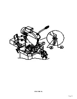
7.1B REPLACING THE SPINDLE IN THE AIR VISE
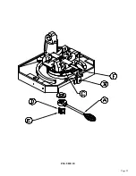
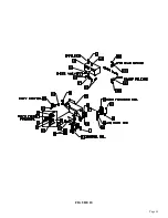
SEE FIGURE 12 ON THE FOLLOWING PAGE.
1.
Disconnect the machine’s power and air supply.
2.
Remove the air lines (A) from the front of the cylinder.
3.
Remove the support block (B), the bolts (C) and the spacer (I) from the base of the vise.
4.
Remove the guide pins (D) out through the back of the vise. The head must be moved to the miter
position in each direction to remove the pins.
5.
Lift the complete vise off of the machine.
6.
Remove the lock nut (J) from the spindle.
7.
Unscrew the vise boss (K) from the spindle.
8.
Unscrew the spindle from the front casting (L) and the rear casting (E).
8.
Install the new spindle and reassemble the vise, reversing the above steps.
FIGURE 12
Summary of Contents for CPO-275
Page 8: ...Page 7 FIGURE 1...
Page 10: ...Page 9 FIGURE 2...
Page 13: ...Page 12 MANUAL OR PK W TRIGGER SWITCH FIGURE 3 1...
Page 14: ...Page 13 PKPD W EMERGENCY STOP FIGURE 3 2...
Page 15: ...Page 14 1 PHASE MOTOR W TRIGGER SWITCH FIGURE 3 3...
Page 16: ...Page 15 1 PHASE MOTOR W E STOP SERIAL S B3431 UP FIGURE 3 4...
Page 22: ...Page 21 FIGURE 5A...
Page 28: ...Page 27 FIGURE 8 FIGURE 9...
Page 30: ...Page 29 FIGURE 10...
Page 36: ...FIGURE 14 Page 35 C A B D...
Page 38: ...Page 37 FIGURE 15...
Page 40: ...Page 39 FIGURE 16...
Page 42: ...Page 41 FIGURE 17...
Page 44: ...Page 43 FIGURE 18...
Page 46: ...Page 45 FIGURE 19...
Page 48: ...Page 47 FIGURE 20...
Page 50: ...Page 49 FIGURE 20A...
Page 58: ...Page 57 FIGURE 23...
Page 60: ...FIGURE 24 Page 59...
Page 62: ...Page 61 G 078000 60 RPM 230 Volt 1 Phase T S 078001 60 RPM 230 Volt 1 Phase E S FIGURE 25...
Page 66: ...Page 65 FIGURE 27...
Page 68: ...Page 67 FIGURE 28...
Page 70: ...Page 69 FIGURE 29...
Page 74: ...Page 73 FIGURE 31...
Page 76: ...Page 75 FIGURE 32...
Page 78: ...Page 77 FIGURE 33...
Page 80: ...FIGURE 34 Page 79...
Page 82: ...Page 81 FIGURE 35...
Page 84: ...Page 83 FIGURE 36...
Page 86: ...Page 85 FIGURE 37...
Page 88: ...Page 87 FIGURE 38...
Page 90: ...Page 89 FIGURE 39...


