Page 11
The CPO-315-HFA saw is equipped with a mist coolant system. A flood coolant system is an
option for this saw.
The container for the coolant is located on the inside of the front door of the saw.
The coolant should be mixed in a ratio of one part coolant to seven parts water. We recommend
using our P/N 075751 coolant (1 gallon) for most applications. This is also available in 5 gallon
bucket as P/N 075752 and in a 55 gallon drum as P/N 075754. This coolant can be mixed stronger
if needed.
When cutting alloy steels such as stainless steel, we recommend our special mix coolant designed
for these applications: P/N 075756 in a 1 gallon jug and P/N 075757 in 5 gallon bucket.
We recommend pre-mixing the coolant before adding it to the saw.
FOR ADDITIONAL INFORMATION ON AVAILABLE COOLANTS, SEE SECTION 12.2.
4.4 COOLANT SYSTEM
5.0 MACHINE START-UP
Before starting this machine, take the time to review the operator.s manual thoroughly, to
familiarize yourself with all of the functions of the machine.
We strongly urge you to follow OSHA directive CFR-1910.147 (effective 09-09-90) regarding
lock-out, tag-out procedures. Keep in mind that the directive refers to all hazardous energy
sources, not just electrical.
The air supply must also be disconnected and locked or tagged.
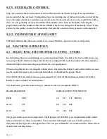
Do not install a blade on the saw until after it has been powered and cycled several times.
Once the machine has been powered, check the rotation of the spindle. There is an arrow on
the guard showing the proper rotation. If the rotation is not correct, the electrician will have
to switch two of the three line wires.
Summary of Contents for CPO-315-HFA-5HP
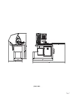
Page 8: ...Page 7 FIGURE 1...
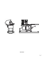
Page 10: ...Page 9 FIGURE 2...
Page 18: ...Page 17 THIS PAGE LEFT BLANK INTENTIONALLY...
Page 19: ...Page 18 6 2 BLADE INSTALLATION SEE FIGURE 4 BELOW FIGURE 4...
Page 23: ...Page 22 6 4 MATERIAL MAIN VISE SEE FIGURE 6 BELOW FIGURE 6...
Page 25: ...Page 24 FIGURE 7...
Page 27: ...Page 26 6 6 POWER DOWN FEED REFER TO FIGURE 8 BELOW FIGURE 8...
Page 30: ...Page 29 FIGURE 9...
Page 31: ...Page 30 6 9 COUNTER SET UP REFER TO FIGURE 10 BELOW FIGURE 10...
Page 37: ...Page 36 8 4 GEAR REPLACEMENT SAW HEAD REFER TO FIGURE 13 BELOW FIGURE 13...
Page 39: ...Page 38 8 5 SPINDLE REPLACEMENT MAIN VISE SEE FIGURE 14 BELOW FIGURE 14...
Page 41: ...Page 40 8 7 SHUTTLE VISE MAINTENANCE SEE FIGURE 15 BELOW FIGURE 15...
Page 46: ...Page 45 FIGURE 17...
Page 58: ......
Page 62: ...Page 61 FIGURE 24...
Page 64: ...Page 63 FIGURE 25...
Page 66: ...Page 65 FIGURE 26...
Page 68: ...Page 67 FIGURE 27...
Page 70: ...Page 69 FIGURE 28...
Page 72: ...Page 71 FIGURE 29...
Page 74: ...Page 73 FIGURE 30...
Page 76: ...Page 75 045345 Scotchman Inds PART NO FIGURE 31 A B D E F G C H I...
Page 77: ......
Page 78: ...Page 77 FIGURE 31B...
Page 80: ...Page 79 FIGURE 32...
Page 82: ...Page 81 FIGURE 33...
Page 83: ......
Page 84: ...Page 83 FIGURE 34...
Page 86: ...Page 85 FIGURE 35...
Page 88: ...Page 87 FIGURE 36...
Page 90: ...Page 89 FIGURE 36...
Page 92: ...Page 91 FIGURE 38...
Page 94: ...Page 93 045345 Scotchman Inds PART NO 14 0 WIRING DIAGRAMS...
Page 95: ...045345 Scotchman Inds PART NO 1 3 Page 94...
Page 97: ...Cont Prev Page Cont Prev Page 045345 Scotchman Inds PART NO 3 3 Page 96...


