Page 13
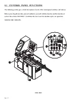
5.1A MAIN POWER SWITCH
This is the main power disconnect switch for the machine and it should be locked or tagged in the OFF
position any time that maintenance or service work is being performed. Maintenance or service work on
the electrical controls must be performed by qualified personnel. This switch must be in the ON position
to operate any of the other control panel functions.
There is a red power indicator light (O) on the control panel. This light indicates that this switch is in
the ON position.
CAUTION: THIS SWITCH DOES NOT DISCONNECT THE AIR SUPPLY TO THE
MACHINE. ANY TIME THAT MAINTENANCE OR SERVICE WORK IS PERFORMED
ON THE MACHINE, THE AIR SUPPLY MUST ALSO BE DISCONNECTED AND TAGGED
OR LOCKED OUT.
5.1B MOTOR CONTROL SWITCH
This switch is used to turn the saw motor on.
5.1C POWER UP SWITCH
This switch energizes the system for the rest of the control panel functions. This switch will also
start the saw motor. The motor will not start unless the MAIN POWER switch (A) is on and the
AUTOMATIC/ MANUAL SWITCH (I) is in the manual position. The MOTOR SWITCH (B) must
be in the ON position for the saw motor to start.
5.1D EMERGENCY STOP SWITCH
This switch stops the saw motor and allows the head to return to the up position. The emergency
stop switch does not release the material vise or the air pressure. Once this switch has been used, the
operator must restart the machine in the manual position and go through the startup procedure again.
For complete instructions on changing bars of material, REFER TO SECTION 7.0.
Summary of Contents for CPO-315-HFA-5HP
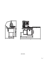
Page 8: ...Page 7 FIGURE 1...
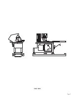
Page 10: ...Page 9 FIGURE 2...
Page 18: ...Page 17 THIS PAGE LEFT BLANK INTENTIONALLY...
Page 19: ...Page 18 6 2 BLADE INSTALLATION SEE FIGURE 4 BELOW FIGURE 4...
Page 23: ...Page 22 6 4 MATERIAL MAIN VISE SEE FIGURE 6 BELOW FIGURE 6...
Page 25: ...Page 24 FIGURE 7...
Page 27: ...Page 26 6 6 POWER DOWN FEED REFER TO FIGURE 8 BELOW FIGURE 8...
Page 30: ...Page 29 FIGURE 9...
Page 31: ...Page 30 6 9 COUNTER SET UP REFER TO FIGURE 10 BELOW FIGURE 10...
Page 37: ...Page 36 8 4 GEAR REPLACEMENT SAW HEAD REFER TO FIGURE 13 BELOW FIGURE 13...
Page 39: ...Page 38 8 5 SPINDLE REPLACEMENT MAIN VISE SEE FIGURE 14 BELOW FIGURE 14...
Page 41: ...Page 40 8 7 SHUTTLE VISE MAINTENANCE SEE FIGURE 15 BELOW FIGURE 15...
Page 46: ...Page 45 FIGURE 17...
Page 58: ......
Page 62: ...Page 61 FIGURE 24...
Page 64: ...Page 63 FIGURE 25...
Page 66: ...Page 65 FIGURE 26...
Page 68: ...Page 67 FIGURE 27...
Page 70: ...Page 69 FIGURE 28...
Page 72: ...Page 71 FIGURE 29...
Page 74: ...Page 73 FIGURE 30...
Page 76: ...Page 75 045345 Scotchman Inds PART NO FIGURE 31 A B D E F G C H I...
Page 77: ......
Page 78: ...Page 77 FIGURE 31B...
Page 80: ...Page 79 FIGURE 32...
Page 82: ...Page 81 FIGURE 33...
Page 83: ......
Page 84: ...Page 83 FIGURE 34...
Page 86: ...Page 85 FIGURE 35...
Page 88: ...Page 87 FIGURE 36...
Page 90: ...Page 89 FIGURE 36...
Page 92: ...Page 91 FIGURE 38...
Page 94: ...Page 93 045345 Scotchman Inds PART NO 14 0 WIRING DIAGRAMS...
Page 95: ...045345 Scotchman Inds PART NO 1 3 Page 94...
Page 97: ...Cont Prev Page Cont Prev Page 045345 Scotchman Inds PART NO 3 3 Page 96...


