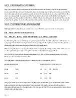
Page 15
5.1J TRIM/TEST
This button is used to do first part cuts prior to running the machine in the automatic position. With the
AUTO/MANUAL switch in the MANUAL position, press the TRIM/TEST button (J) and then, press
the CYCLE button (H). The saw will trim and then cut one part and return to the up position. Make
whatever adjustments that you need to and depress the CYCLE button (H) again and the saw will cut one
more test piece. After you are satisfied with all of the settings, place the AUTO/MANUAL switch (I) in
the AUTOMATIC position and press the CYCLE button again. The saw will start the automatic
operation.
5.1K COOLANT PUMP SWITCH
This switch starts the machine’s coolant pump.
5.1L VARIABLE MOTOR SPEED CONTROL
This switch is one of the most important standard features on this machine. This switch gives you a wide
range of cutting speeds. The range is from 11 RPM to 177 RPM. With this feature, you are able to match
the blade speed to the material, which greatly increases blade life and reduces vibrations. When this
switch is in the 50 percent position, the machine runs at 83 RPM. With the switch at the 0 percent
position, the RPM’S will be 11 and with the switch at the 100 percent position, the RPM’S will be 177.
5.1M COUNTER
The Parts Counter is programmed at the factory to count up. If you want to set the counter to count
down, please contact the factory. To enter a pre-set value in the counter, press any of the white keys
numbered 1 to 5. The pre-set value will appear on the screen. Use the white keys to set the total number
of pieces that you want to cut. After a three second delay, the pre-set value screen will disappear. The
counter will then display the number of pieces cut as the saw runs. When the value on the screen reaches
the pre-set value, the machine will stop. If you press the red button, the count value displayed on the
screen will be zeroed out. The reset button does not erase the pre-set value. To change the pre-set value,
press any white button and the pre-set value will appear on the screen. For the machine to run in the
automatic mode, there must be a pre-set value on the counter.
Summary of Contents for CPO-315-HFA-5HP
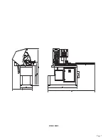
Page 8: ...Page 7 FIGURE 1...
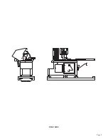
Page 10: ...Page 9 FIGURE 2...
Page 18: ...Page 17 THIS PAGE LEFT BLANK INTENTIONALLY...
Page 19: ...Page 18 6 2 BLADE INSTALLATION SEE FIGURE 4 BELOW FIGURE 4...
Page 23: ...Page 22 6 4 MATERIAL MAIN VISE SEE FIGURE 6 BELOW FIGURE 6...
Page 25: ...Page 24 FIGURE 7...
Page 27: ...Page 26 6 6 POWER DOWN FEED REFER TO FIGURE 8 BELOW FIGURE 8...
Page 30: ...Page 29 FIGURE 9...
Page 31: ...Page 30 6 9 COUNTER SET UP REFER TO FIGURE 10 BELOW FIGURE 10...
Page 37: ...Page 36 8 4 GEAR REPLACEMENT SAW HEAD REFER TO FIGURE 13 BELOW FIGURE 13...
Page 39: ...Page 38 8 5 SPINDLE REPLACEMENT MAIN VISE SEE FIGURE 14 BELOW FIGURE 14...
Page 41: ...Page 40 8 7 SHUTTLE VISE MAINTENANCE SEE FIGURE 15 BELOW FIGURE 15...
Page 46: ...Page 45 FIGURE 17...
Page 58: ......
Page 62: ...Page 61 FIGURE 24...
Page 64: ...Page 63 FIGURE 25...
Page 66: ...Page 65 FIGURE 26...
Page 68: ...Page 67 FIGURE 27...
Page 70: ...Page 69 FIGURE 28...
Page 72: ...Page 71 FIGURE 29...
Page 74: ...Page 73 FIGURE 30...
Page 76: ...Page 75 045345 Scotchman Inds PART NO FIGURE 31 A B D E F G C H I...
Page 77: ......
Page 78: ...Page 77 FIGURE 31B...
Page 80: ...Page 79 FIGURE 32...
Page 82: ...Page 81 FIGURE 33...
Page 83: ......
Page 84: ...Page 83 FIGURE 34...
Page 86: ...Page 85 FIGURE 35...
Page 88: ...Page 87 FIGURE 36...
Page 90: ...Page 89 FIGURE 36...
Page 92: ...Page 91 FIGURE 38...
Page 94: ...Page 93 045345 Scotchman Inds PART NO 14 0 WIRING DIAGRAMS...
Page 95: ...045345 Scotchman Inds PART NO 1 3 Page 94...
Page 97: ...Cont Prev Page Cont Prev Page 045345 Scotchman Inds PART NO 3 3 Page 96...


