Page 16
5.1N FEED RATE CONTROL
This valve controls the down feed rate of the saw head and is used in the set-up of the up and down
stroke control of the saw head. To adjust the down feed cutting rate of the head, turn the control all the
way to the right (clockwise) and then, open it one turn. The down feed rate is set by sound. Start with a
slow rate and gradually increase it until the blade chatters, then back it off slightly. Selecting the
proper blade and the condition of the blade will effect the down cutting rate dramatically. There is also
a down feed regulator, located on the machine, that provides constant down pressure on the material.
5.1O POWER INDICATOR LIGHT
This light indicates that the main switch (A) is on and that there is power to the control panel.
6.0 MACHINE OPERATION
6.1 SELECTING THE PROPER CUTTING SPEED
In cold sawing, there is no such thing as a general purpose blade. To achieve the best results from your
saw, proper blade selection is important. Each saw is shipped with a pitch (number of teeth) calculator,
which will help to determine the proper blade for your application.
When sawing flat stock or rectangular solid sections, determine the thickest section that will be cut and
use the equivalent square size on the pitch calculator to determine the proper blade.
The CPO-315-HFA is designed to use a maximum 12-1/2 inch (315mm) diameter blade. 10-3/4 inch
blades are also available for this machine.
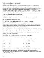
The chart below gives the surface feet per minute for the various spindle RPM’S:
BLADE DIAMETER
SURFACE FEET PER MINUTE
INCH
MM
18
88 176 RPM’S
10-3/4
275
50 247 495
12-1/2
315
59 287 576
The proper blade speed is also important. The High speed (176 RPM) is recommended for thin walled
tubes and nonferrous tubes and profiles. Some materials will require test cuts at both speeds to
determine the best speed for the application. The Low speed, 18 RPM, is recommended for solid sections
of mild steel and alloy tubes.
Summary of Contents for CPO-315-HFA-5HP
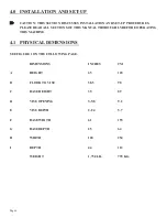
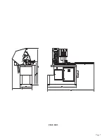
Page 8: ...Page 7 FIGURE 1...
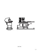
Page 10: ...Page 9 FIGURE 2...
Page 18: ...Page 17 THIS PAGE LEFT BLANK INTENTIONALLY...
Page 19: ...Page 18 6 2 BLADE INSTALLATION SEE FIGURE 4 BELOW FIGURE 4...
Page 23: ...Page 22 6 4 MATERIAL MAIN VISE SEE FIGURE 6 BELOW FIGURE 6...
Page 25: ...Page 24 FIGURE 7...
Page 27: ...Page 26 6 6 POWER DOWN FEED REFER TO FIGURE 8 BELOW FIGURE 8...
Page 30: ...Page 29 FIGURE 9...
Page 31: ...Page 30 6 9 COUNTER SET UP REFER TO FIGURE 10 BELOW FIGURE 10...
Page 37: ...Page 36 8 4 GEAR REPLACEMENT SAW HEAD REFER TO FIGURE 13 BELOW FIGURE 13...
Page 39: ...Page 38 8 5 SPINDLE REPLACEMENT MAIN VISE SEE FIGURE 14 BELOW FIGURE 14...
Page 41: ...Page 40 8 7 SHUTTLE VISE MAINTENANCE SEE FIGURE 15 BELOW FIGURE 15...
Page 46: ...Page 45 FIGURE 17...
Page 58: ......
Page 62: ...Page 61 FIGURE 24...
Page 64: ...Page 63 FIGURE 25...
Page 66: ...Page 65 FIGURE 26...
Page 68: ...Page 67 FIGURE 27...
Page 70: ...Page 69 FIGURE 28...
Page 72: ...Page 71 FIGURE 29...
Page 74: ...Page 73 FIGURE 30...
Page 76: ...Page 75 045345 Scotchman Inds PART NO FIGURE 31 A B D E F G C H I...
Page 77: ......
Page 78: ...Page 77 FIGURE 31B...
Page 80: ...Page 79 FIGURE 32...
Page 82: ...Page 81 FIGURE 33...
Page 83: ......
Page 84: ...Page 83 FIGURE 34...
Page 86: ...Page 85 FIGURE 35...
Page 88: ...Page 87 FIGURE 36...
Page 90: ...Page 89 FIGURE 36...
Page 92: ...Page 91 FIGURE 38...
Page 94: ...Page 93 045345 Scotchman Inds PART NO 14 0 WIRING DIAGRAMS...
Page 95: ...045345 Scotchman Inds PART NO 1 3 Page 94...
Page 97: ...Cont Prev Page Cont Prev Page 045345 Scotchman Inds PART NO 3 3 Page 96...

