Page 20
10.
Adjust the blade guide bolts (G), if required. These guides are required only when the blade has a
small amount of deflection in it or when a very exact cut is required. Adjust the inside, or right
hand bolt, first. The bolt should be adjusted up to where it just touches the blade as close to the
teeth as possible and lock the retaining nut. Do not adjust the bolt to where it deflects the blade.
Over adjustment of the guide bolt will cause the blade not to run true and will cause excessive
wear. After the inside bolt is adjusted, move the outside bolt to where it is straight across from the
inside one. Adjust the outside bolt up to where it just touches the blade and then, lock the
retaining nut.
11.
Reset the upper stroke control and return the movable hood guard to the down position.
12.
Break in the saw blade. The teeth on new or re-sharpened blades have a very sharp edge and
should be fed through the first three or four cuts, very slowly, before starting normal cutting.
Besides taking up the back lash and breaking in the blade, it is very important to keep the blade
flange, the spindle and the blade clean and free from nicks. Failure to do these things will result in
broken or damaged blades.
Summary of Contents for CPO-315-HFA-5HP
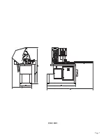
Page 8: ...Page 7 FIGURE 1...
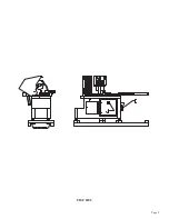
Page 10: ...Page 9 FIGURE 2...
Page 18: ...Page 17 THIS PAGE LEFT BLANK INTENTIONALLY...
Page 19: ...Page 18 6 2 BLADE INSTALLATION SEE FIGURE 4 BELOW FIGURE 4...
Page 23: ...Page 22 6 4 MATERIAL MAIN VISE SEE FIGURE 6 BELOW FIGURE 6...
Page 25: ...Page 24 FIGURE 7...
Page 27: ...Page 26 6 6 POWER DOWN FEED REFER TO FIGURE 8 BELOW FIGURE 8...
Page 30: ...Page 29 FIGURE 9...
Page 31: ...Page 30 6 9 COUNTER SET UP REFER TO FIGURE 10 BELOW FIGURE 10...
Page 37: ...Page 36 8 4 GEAR REPLACEMENT SAW HEAD REFER TO FIGURE 13 BELOW FIGURE 13...
Page 39: ...Page 38 8 5 SPINDLE REPLACEMENT MAIN VISE SEE FIGURE 14 BELOW FIGURE 14...
Page 41: ...Page 40 8 7 SHUTTLE VISE MAINTENANCE SEE FIGURE 15 BELOW FIGURE 15...
Page 46: ...Page 45 FIGURE 17...
Page 58: ......
Page 62: ...Page 61 FIGURE 24...
Page 64: ...Page 63 FIGURE 25...
Page 66: ...Page 65 FIGURE 26...
Page 68: ...Page 67 FIGURE 27...
Page 70: ...Page 69 FIGURE 28...
Page 72: ...Page 71 FIGURE 29...
Page 74: ...Page 73 FIGURE 30...
Page 76: ...Page 75 045345 Scotchman Inds PART NO FIGURE 31 A B D E F G C H I...
Page 77: ......
Page 78: ...Page 77 FIGURE 31B...
Page 80: ...Page 79 FIGURE 32...
Page 82: ...Page 81 FIGURE 33...
Page 83: ......
Page 84: ...Page 83 FIGURE 34...
Page 86: ...Page 85 FIGURE 35...
Page 88: ...Page 87 FIGURE 36...
Page 90: ...Page 89 FIGURE 36...
Page 92: ...Page 91 FIGURE 38...
Page 94: ...Page 93 045345 Scotchman Inds PART NO 14 0 WIRING DIAGRAMS...
Page 95: ...045345 Scotchman Inds PART NO 1 3 Page 94...
Page 97: ...Cont Prev Page Cont Prev Page 045345 Scotchman Inds PART NO 3 3 Page 96...

