Page 27
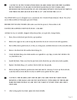
CAUTION: ALWAYS DISCONNECT THE AIR SUPPLY BEFORE REMOVING THE FILLER
PLUG FROM THE RESERVOIR. IF THE FILLER PLUG IS REMOVED WHILE THE
MACHINE IS CONNECTED TO AIR PRESSURE, THE FLUID IN THE TANK WILL BE
PURGED THROUGH THE OPENING UNDER PRESSURE.
1.
BEFORE POWERING THE SAW, check the oil level in the reservoir (A). It should be
approximately 2-1/2 inches below the top of the reservoir when the saw head is in the UP position.
Over filling the reservoir will cause hydraulic oil to be forced into the air system. The
recommended oil is a 10 WT., non-foaming, hydraulic oil such as Cenex (CEN-LUBE RO AW
150).
2.
Slide the shuttle valve (C) to its CLOSED position and connect the air supply.
3.
Slide the shuttle valve to its OPEN position and shut the flow control valve (B) off. Then, open it
one turn.
4.
The down feed rate is adjusted using the flow control valve (B). The down feed rate should be set
during the setup of an operation while the AUTOMATIC/MANUAL switch is in the MANUAL
position. The setting of the down feed rate is done by sound. Slowly adjust the rate as the saw
makes a cut. Once the blade starts to chatter or the saw starts to load up, back the rate off by 1/4
of a turn.
Many things, including the type of material being cut, the blade RPM and the condition of the
blade, will affect the down feed rate.
Summary of Contents for CPO-315-HFA-5HP
Page 8: ...Page 7 FIGURE 1...
Page 10: ...Page 9 FIGURE 2...
Page 18: ...Page 17 THIS PAGE LEFT BLANK INTENTIONALLY...
Page 19: ...Page 18 6 2 BLADE INSTALLATION SEE FIGURE 4 BELOW FIGURE 4...
Page 23: ...Page 22 6 4 MATERIAL MAIN VISE SEE FIGURE 6 BELOW FIGURE 6...
Page 25: ...Page 24 FIGURE 7...
Page 27: ...Page 26 6 6 POWER DOWN FEED REFER TO FIGURE 8 BELOW FIGURE 8...
Page 30: ...Page 29 FIGURE 9...
Page 31: ...Page 30 6 9 COUNTER SET UP REFER TO FIGURE 10 BELOW FIGURE 10...
Page 37: ...Page 36 8 4 GEAR REPLACEMENT SAW HEAD REFER TO FIGURE 13 BELOW FIGURE 13...
Page 39: ...Page 38 8 5 SPINDLE REPLACEMENT MAIN VISE SEE FIGURE 14 BELOW FIGURE 14...
Page 41: ...Page 40 8 7 SHUTTLE VISE MAINTENANCE SEE FIGURE 15 BELOW FIGURE 15...
Page 46: ...Page 45 FIGURE 17...
Page 58: ......
Page 62: ...Page 61 FIGURE 24...
Page 64: ...Page 63 FIGURE 25...
Page 66: ...Page 65 FIGURE 26...
Page 68: ...Page 67 FIGURE 27...
Page 70: ...Page 69 FIGURE 28...
Page 72: ...Page 71 FIGURE 29...
Page 74: ...Page 73 FIGURE 30...
Page 76: ...Page 75 045345 Scotchman Inds PART NO FIGURE 31 A B D E F G C H I...
Page 77: ......
Page 78: ...Page 77 FIGURE 31B...
Page 80: ...Page 79 FIGURE 32...
Page 82: ...Page 81 FIGURE 33...
Page 83: ......
Page 84: ...Page 83 FIGURE 34...
Page 86: ...Page 85 FIGURE 35...
Page 88: ...Page 87 FIGURE 36...
Page 90: ...Page 89 FIGURE 36...
Page 92: ...Page 91 FIGURE 38...
Page 94: ...Page 93 045345 Scotchman Inds PART NO 14 0 WIRING DIAGRAMS...
Page 95: ...045345 Scotchman Inds PART NO 1 3 Page 94...
Page 97: ...Cont Prev Page Cont Prev Page 045345 Scotchman Inds PART NO 3 3 Page 96...


