Page 41
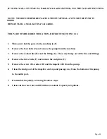
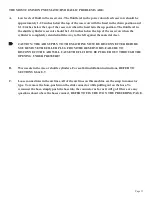
TO REPLACE THE VISE SPINDLE:
1.
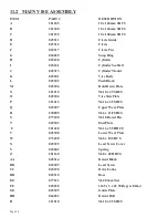
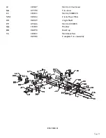
Remove the jam nut (GG), the set screw (H), the spring (FF) and the ball (G).
2.
Remove the jam nut (A) and the boss (B) from the end of the spindle.
3.
Disconnect the air lines and the proximity switch from the cylinder. The air connections on the
cylinder are snap connectors. To release the air connections, push the collar around the hose into
the fitting and pull the hose out. To reconnect the lines, simply push the air line into the fitting as
far as it will go easily.
4.
Remove the four bolts (Z) from the cylinder end plate and remove the cylinder assembly from the
machine.
5.
Slide the vise spindle (K) and vise block (L) off of the machine and replace either part, as needed.
6.
Reassemble the vise, reversing the above steps.
IF YOU NEED TO REPLACE THE SEALS IN THE AIR CYLINDER:
1.
After step number 4 above, clamp the end plate (D) in a vise and remove the four bolts (PP).
2.
Slide the end plate (AA) off and remove the piston (CC) and the cylinder tube (C).
3.
Replace the seals and reassemble, reversing the above steps.
Summary of Contents for CPO-315-HFA-5HP
Page 8: ...Page 7 FIGURE 1...
Page 10: ...Page 9 FIGURE 2...
Page 18: ...Page 17 THIS PAGE LEFT BLANK INTENTIONALLY...
Page 19: ...Page 18 6 2 BLADE INSTALLATION SEE FIGURE 4 BELOW FIGURE 4...
Page 23: ...Page 22 6 4 MATERIAL MAIN VISE SEE FIGURE 6 BELOW FIGURE 6...
Page 25: ...Page 24 FIGURE 7...
Page 27: ...Page 26 6 6 POWER DOWN FEED REFER TO FIGURE 8 BELOW FIGURE 8...
Page 30: ...Page 29 FIGURE 9...
Page 31: ...Page 30 6 9 COUNTER SET UP REFER TO FIGURE 10 BELOW FIGURE 10...
Page 37: ...Page 36 8 4 GEAR REPLACEMENT SAW HEAD REFER TO FIGURE 13 BELOW FIGURE 13...
Page 39: ...Page 38 8 5 SPINDLE REPLACEMENT MAIN VISE SEE FIGURE 14 BELOW FIGURE 14...
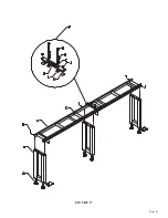
Page 41: ...Page 40 8 7 SHUTTLE VISE MAINTENANCE SEE FIGURE 15 BELOW FIGURE 15...
Page 46: ...Page 45 FIGURE 17...
Page 58: ......
Page 62: ...Page 61 FIGURE 24...
Page 64: ...Page 63 FIGURE 25...
Page 66: ...Page 65 FIGURE 26...
Page 68: ...Page 67 FIGURE 27...
Page 70: ...Page 69 FIGURE 28...
Page 72: ...Page 71 FIGURE 29...
Page 74: ...Page 73 FIGURE 30...
Page 76: ...Page 75 045345 Scotchman Inds PART NO FIGURE 31 A B D E F G C H I...
Page 77: ......
Page 78: ...Page 77 FIGURE 31B...
Page 80: ...Page 79 FIGURE 32...
Page 82: ...Page 81 FIGURE 33...
Page 83: ......
Page 84: ...Page 83 FIGURE 34...
Page 86: ...Page 85 FIGURE 35...
Page 88: ...Page 87 FIGURE 36...
Page 90: ...Page 89 FIGURE 36...
Page 92: ...Page 91 FIGURE 38...
Page 94: ...Page 93 045345 Scotchman Inds PART NO 14 0 WIRING DIAGRAMS...
Page 95: ...045345 Scotchman Inds PART NO 1 3 Page 94...
Page 97: ...Cont Prev Page Cont Prev Page 045345 Scotchman Inds PART NO 3 3 Page 96...

