Page 48
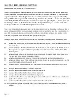
10.5 PLC TROUBLESHOOTING
SEE FIGURE 18 ON THE FOLLOWING PAGE.
The PLC on this machine has a readable screen on it that can be used to diagnose most problems that
you may encounter with the machine. The main controller has 12 inputs numbered I-1 to I-12 and six
outputs numbered Q-1 through Q-6. It also has an auxiliary controller with 12 inputs numbered R-1
through R-12 and six outputs numbered S-1 through S-6. When the controller is first powered, the RUN
and CAW light will flash red; when the controller is ready, the run light will glow a constant green and
the other light will not be lit. On the main controller, the inputs I-7 through I-12 are not used; on the
auxiliary controller, the inputs R-10 through R-12 are not used.
To see which inputs and outputs are active on the main controller, press the esc key on the controller. A
screen will appear with the input and output numbers on the screen for the ones that are activated. To
see which inputs and outputs are active on the auxiliary controller, press the esc and aux key on the
controller. To go back to the main controller, just press esc again.
The input lights are listed here. The ouputs will vary, depending on what position the machine is in.
I-1
is the e-stop switch. This should be activated anytime there is power to the machine and the e-stop
is not activated.
I-2
is the input for the shuttle out limit switch. It should only be activated when the shuttle vise is in
the out position, ready to feed the next part. This sensor is located on the outboard end of the
shuttle cylinder.
I-3
is the shuttle in indicator. It should only be activated when the shuttle vise is in the in position.
This sensor is in the body of the shuttle cylinder.
I-4
is the head up limit switch indicator. This will be on when the head is in the up position.
I-5
is the material out sensor. This will be activated when there is no material in the shuttle vise. The
sensor for this is located in the shuttle itself.
I-6
is the head down limit switch indicator. This will be on when the head is in the down position.
R-1
is only activated when the cycle button is depressed.
R-2
is only activated when the head down button is depressed.
R-3
is only activated when the head up button is depressed.
R-4
is only activated when the trim/test button is depressed.
R-5
is activated when there is a count on the parts counter. The machine will not operate in the auto
mode if the counter is at zero.
R-6
is activated when the Auto/Start/Manual switch is in the Auto position.
R-7, R-8 and R-9 are for the index switch. R-7 is for 1 index, R-8 is for two indexes and R-9 is for 3
indexes.
Summary of Contents for CPO-315-HFA-5HP
Page 8: ...Page 7 FIGURE 1...
Page 10: ...Page 9 FIGURE 2...
Page 18: ...Page 17 THIS PAGE LEFT BLANK INTENTIONALLY...
Page 19: ...Page 18 6 2 BLADE INSTALLATION SEE FIGURE 4 BELOW FIGURE 4...
Page 23: ...Page 22 6 4 MATERIAL MAIN VISE SEE FIGURE 6 BELOW FIGURE 6...
Page 25: ...Page 24 FIGURE 7...
Page 27: ...Page 26 6 6 POWER DOWN FEED REFER TO FIGURE 8 BELOW FIGURE 8...
Page 30: ...Page 29 FIGURE 9...
Page 31: ...Page 30 6 9 COUNTER SET UP REFER TO FIGURE 10 BELOW FIGURE 10...
Page 37: ...Page 36 8 4 GEAR REPLACEMENT SAW HEAD REFER TO FIGURE 13 BELOW FIGURE 13...
Page 39: ...Page 38 8 5 SPINDLE REPLACEMENT MAIN VISE SEE FIGURE 14 BELOW FIGURE 14...
Page 41: ...Page 40 8 7 SHUTTLE VISE MAINTENANCE SEE FIGURE 15 BELOW FIGURE 15...
Page 46: ...Page 45 FIGURE 17...
Page 58: ......
Page 62: ...Page 61 FIGURE 24...
Page 64: ...Page 63 FIGURE 25...
Page 66: ...Page 65 FIGURE 26...
Page 68: ...Page 67 FIGURE 27...
Page 70: ...Page 69 FIGURE 28...
Page 72: ...Page 71 FIGURE 29...
Page 74: ...Page 73 FIGURE 30...
Page 76: ...Page 75 045345 Scotchman Inds PART NO FIGURE 31 A B D E F G C H I...
Page 77: ......
Page 78: ...Page 77 FIGURE 31B...
Page 80: ...Page 79 FIGURE 32...
Page 82: ...Page 81 FIGURE 33...
Page 83: ......
Page 84: ...Page 83 FIGURE 34...
Page 86: ...Page 85 FIGURE 35...
Page 88: ...Page 87 FIGURE 36...
Page 90: ...Page 89 FIGURE 36...
Page 92: ...Page 91 FIGURE 38...
Page 94: ...Page 93 045345 Scotchman Inds PART NO 14 0 WIRING DIAGRAMS...
Page 95: ...045345 Scotchman Inds PART NO 1 3 Page 94...
Page 97: ...Cont Prev Page Cont Prev Page 045345 Scotchman Inds PART NO 3 3 Page 96...


