Page 8
4.2 MACHINE INSTALLATION
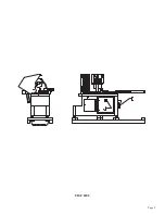
SEE FIGURE 2 ON THE FOLLOWING PAGE.
This machine is shipped on a pallet and can be moved to the installation location by means of a forklift.
CAUTION: THIS MACHINE IS TOP HEAVY AND MUST BE MOVED WITH CARE, ON
HARD FLAT SURFACES ONLY.
USE THE FOLLOWING STEPS TO INSTALL THE MACHINE:
1.
Select a location for the machine that allows adequate room for any length of material that
you may want to cut. Leave adequate space behind the machine and on either end, for set-up
and maintenance.
2.
Lift the machine off of the shipping pallet, using a forklift.
3.
Place the machine in its final location and level it, using the leveling pads. For this machine to
function properly, it is very important that it is level. Any supply tracks used with this machine
must also be level and aligned with the vises on the machine.
4.
Install the shuttle cylinder on the machine.
NOTE: MACHINES EQUIPPED WITH A DIGITAL READOUT WILL ALREADY HAVE THE
CYLINDER INSTALLED.
5.
We strongly recommend that you anchor the machine and supply tracks to the floor, with the
anchor plates provided with the machine.
6.
Connect the main air and electrical supply lines to the machine. To connect the air, slide the
shuttle valve (I) down to the closed position and connect the incoming supply line. (DO NOT
TURN THE AIR ON YET.) This machine requires a minimum of 90 PSI and may require up to
130 PSI, depending on your application. The electrical supply lines must be connected by a
qualified electrician. The supply lines connect to the top of the main disconnect switch (J) located
in the lower base cabinet. Make sure that your plant phase and voltage correspond to the phase
and voltage of the machine before connecting the electrical supply.
CAUTION: DO NOT POWER THE MACHINE UNTIL THE MACHINE INSTALLATION IS
COMPLETE AND UNTIL YOU HAVE READ ALL OF THE SECTIONS OF THIS MANUAL!
Summary of Contents for CPO-315-HFA-5HP
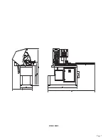
Page 8: ...Page 7 FIGURE 1...
Page 10: ...Page 9 FIGURE 2...
Page 18: ...Page 17 THIS PAGE LEFT BLANK INTENTIONALLY...
Page 19: ...Page 18 6 2 BLADE INSTALLATION SEE FIGURE 4 BELOW FIGURE 4...
Page 23: ...Page 22 6 4 MATERIAL MAIN VISE SEE FIGURE 6 BELOW FIGURE 6...
Page 25: ...Page 24 FIGURE 7...
Page 27: ...Page 26 6 6 POWER DOWN FEED REFER TO FIGURE 8 BELOW FIGURE 8...
Page 30: ...Page 29 FIGURE 9...
Page 31: ...Page 30 6 9 COUNTER SET UP REFER TO FIGURE 10 BELOW FIGURE 10...
Page 37: ...Page 36 8 4 GEAR REPLACEMENT SAW HEAD REFER TO FIGURE 13 BELOW FIGURE 13...
Page 39: ...Page 38 8 5 SPINDLE REPLACEMENT MAIN VISE SEE FIGURE 14 BELOW FIGURE 14...
Page 41: ...Page 40 8 7 SHUTTLE VISE MAINTENANCE SEE FIGURE 15 BELOW FIGURE 15...
Page 46: ...Page 45 FIGURE 17...
Page 58: ......
Page 62: ...Page 61 FIGURE 24...
Page 64: ...Page 63 FIGURE 25...
Page 66: ...Page 65 FIGURE 26...
Page 68: ...Page 67 FIGURE 27...
Page 70: ...Page 69 FIGURE 28...
Page 72: ...Page 71 FIGURE 29...
Page 74: ...Page 73 FIGURE 30...
Page 76: ...Page 75 045345 Scotchman Inds PART NO FIGURE 31 A B D E F G C H I...
Page 77: ......
Page 78: ...Page 77 FIGURE 31B...
Page 80: ...Page 79 FIGURE 32...
Page 82: ...Page 81 FIGURE 33...
Page 83: ......
Page 84: ...Page 83 FIGURE 34...
Page 86: ...Page 85 FIGURE 35...
Page 88: ...Page 87 FIGURE 36...
Page 90: ...Page 89 FIGURE 36...
Page 92: ...Page 91 FIGURE 38...
Page 94: ...Page 93 045345 Scotchman Inds PART NO 14 0 WIRING DIAGRAMS...
Page 95: ...045345 Scotchman Inds PART NO 1 3 Page 94...
Page 97: ...Cont Prev Page Cont Prev Page 045345 Scotchman Inds PART NO 3 3 Page 96...


