background image

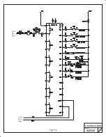
Page 89

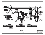
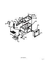
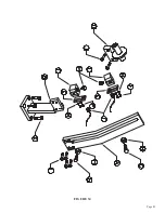
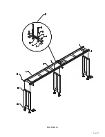
FIGURE 36

Summary of Contents for CPO-315-HFA-5HP

Page 1: ...You have downloaded a manual for our MODEL CPO 315 HFA 5HP COLD SAW Please download our Cold Sawing Guide too Read both the manual and guide before operating this saw...

Page 2: ...MODEL CPO 315 HFA 5HP COLD SAW PRINTED MAY 2021 www scotchman com SCOTCHMAN IND 180 E US HWY 14 PO BOX 850 PHILIP SD 57567 Call 1 605 859 2542...

Page 3: ...he Proper Blade and Cutting Speed 16 6 2 Blade Installation 18 6 3 Saw Capacities 21 6 4 Main Vise 22 6 5 Shuttle Vise 25 6 6 Power Down Feed 26 6 7 Material Clamping 28 6 8 Stroke Control Adjustment...

Page 4: ...1 6A 11 6B 11 7 11 8 Air Valve Assembly Blade Guard Assembly 11 9 11 10 11 11 11 12 Electrical Unit Line Circuit Electrical Unit Secondary Circuit Base Assembly 11 13 11 14 12 0 12 1 12 2 13 0 14 0 St...

Page 5: ...e diameter of the blade will no longer cut through the material The vise allows for easy changeover to special clamping jaws for profiles and extrusions Having a motor variable speed control enables t...

Page 6: ...e seller s option returns the defective goods freight and delivery prepaid to the seller which shall be the buyer s sole and exclusive remedy for defective goods Hydraulic and electrical components ar...

Page 7: ...IS MANUAL THOROUGHLY BEFORE OPERATING THIS MACHINE 4 1 PHYSICAL DIMENSIONS SEE FIGURE 1 ON THE FOLLOWING PAGE DIMENSIONS INCHES CM A HEIGHT 65 165 B FLOOR TO VISE 38 5 98 C BASE HEIGHT 35 89 D VISE OP...

Page 8: ...Page 7 FIGURE 1...

Page 9: ...chine 4 Install the shuttle cylinder on the machine NOTE MACHINES EQUIPPED WITH A DIGITAL READOUT WILL ALREADY HAVE THE CYLINDER INSTALLED 5 We strongly recommend that you anchor the machine and suppl...

Page 10: ...Page 9 FIGURE 2...

Page 11: ...tisfactory performance the supply voltage should be or 10 of the motor voltage rating Check the motor data tag for full load current requirements Single phase motors are not available NOTE MACHINES TH...

Page 12: ...re mixing the coolant before adding it to the saw FOR ADDITIONAL INFORMATION ON AVAILABLE COOLANTS SEE SECTION 12 2 4 4 COOLANT SYSTEM 5 0 MACHINE START UP Before starting this machine take the time t...

Page 13: ...description of each of the control panel switches and buttons Before powering the machine please familiarize yourself with the location and the function of each of these items SECTION 7 0 will describ...

Page 14: ...PLY MUST ALSO BE DISCONNECTED AND TAGGED OR LOCKED OUT 5 1B MOTOR CONTROL SWITCH This switch is used to turn the saw motor on 5 1C POWER UP SWITCH This switch energizes the system for the rest of the...

Page 15: ...NUAL position to start the machine to make trim cuts and to set the product lengths After the machine has been set up and sample cuts have been made this switch is moved to the AUTOMATIC position Any...

Page 16: ...ich greatly increases blade life and reduces vibrations When this switch is in the 50 percent position the machine runs at 83 RPM With the switch at the 0 percent position the RPM S will be 11 and wit...

Page 17: ...as a general purpose blade To achieve the best results from your saw proper blade selection is important Each saw is shipped with a pitch number of teeth calculator which will help to determine the pr...

Page 18: ...Page 17 THIS PAGE LEFT BLANK INTENTIONALLY...

Page 19: ...Page 18 6 2 BLADE INSTALLATION SEE FIGURE 4 BELOW FIGURE 4...

Page 20: ...the head to travel to its full up position 3 Back off the blade guide bolts G if they are being used and slide them out to the end of the slots 4 Remove the blade bolt B and the blade flange C 5 Check...

Page 21: ...After the inside bolt is adjusted move the outside bolt to where it is straight across from the inside one Adjust the outside bolt up to where it just touches the blade and then lock the retaining nu...

Page 22: ...047200 HFA 90 ONLY 3 76 3 76 3 1 2 89 2 1 2 X 2 1 2 63 X 63 3 1 8 X 3 1 8 79 X 79 N A N A FERROUS FERROUS NF NF 2 1 2 X 2 1 2 63 X 63 2 1 2 X 2 1 2 63 X 63 3 1 8 X 3 1 8 79 X 79 2 1 2 X 2 1 2 63 X 63...

Page 23: ...Page 22 6 4 MATERIAL MAIN VISE SEE FIGURE 6 BELOW FIGURE 6...

Page 24: ...lubricating device A should release one drop of oil every 5 to 10 cycles On top of the lubricating device is a clear plastic dome with a small tube inside The oil should drop out of the tube The lubri...

Page 25: ...Page 24 FIGURE 7...

Page 26: ...such as Mobil DTE 10 or equivalent The following are set up and maintenance instructions for the shuttle assembly 1 Steps 1 through 8 are the same for the shuttle vise as they are for the material vis...

Page 27: ...Page 26 6 6 POWER DOWN FEED REFER TO FIGURE 8 BELOW FIGURE 8...

Page 28: ...ing hydraulic oil such as Cenex CEN LUBE RO AW 150 2 Slide the shuttle valve C to its CLOSED position and connect the air supply 3 Slide the shuttle valve to its OPEN position and shut the flow contro...

Page 29: ...slot 3 Place a piece of the material that you are going to cut in the saw vise and manually clamp it in a position so that the saw blade will not contact the material when the head comes down 4 Close...

Page 30: ...Page 29 FIGURE 9...

Page 31: ...Page 30 6 9 COUNTER SET UP REFER TO FIGURE 10 BELOW FIGURE 10...

Page 32: ...to cut After a three second delay the pre set value screen will disappear The counter will then display the number of pieces cut as the saw runs When the value on the screen reaches the pre set value...

Page 33: ...C OPERATION SET UP REFER TO FIGURE 11 BELOW The following instructions are to set up a job for automatic operation Make sure that you are familiar with the functions of all of the switches and buttons...

Page 34: ...le it is making the first cut 10 Check the accuracy of the first part and make any adjustments required The fine adjustment knob O will change the length of the part by 1 5 thousandths of an inch per...

Page 35: ...erature bearing grease daily Apply oil to the shuttle vise guide shafts daily Clean the chips out of the vise at least once a day more often if needed Apply penetrating oil to the spindle and guide pi...

Page 36: ...set up and documented according to your application and the frequency you use this machine The following is a list of some important things that should be included in a scheduled maintenance program 1...

Page 37: ...Page 36 8 4 GEAR REPLACEMENT SAW HEAD REFER TO FIGURE 13 BELOW FIGURE 13...

Page 38: ...removed by driving it out with a brass drift pin 5 Inspect the worm shaft drive gear and bearings for wear 6 After the worm shaft has been removed remove the three bolts M from the bearing housing O 7...

Page 39: ...Page 38 8 5 SPINDLE REPLACEMENT MAIN VISE SEE FIGURE 14 BELOW FIGURE 14...

Page 40: ...reassemble the vise reversing the above steps 8 6 SEAL REPLACEMENT MAIN VISE SEE FIGURE 14 ON THE PRECEDING PAGE 1 Make sure that the power and air supply to the machine are both off 2 Remove the bol...

Page 41: ...Page 40 8 7 SHUTTLE VISE MAINTENANCE SEE FIGURE 15 BELOW FIGURE 15...

Page 42: ...the lines simply push the air line into the fitting as far as it will go easily 4 Remove the four bolts Z from the cylinder end plate and remove the cylinder assembly from the machine 5 Slide the vis...

Page 43: ...OPTINAL FLOOD COOLANT SEE FIGURE 16 BELOW 8 8 COOLANT PUMP MAINTENANCE Page 42 FIGURE 16 F E D A I J H K B C...

Page 44: ...four bolts J and remove the pump from the machine 3 Remove the coolant line H and the fitting G Clean any sludge out of the line and fittings 4 Remove the three bolts F and remove the end plate C 5 R...

Page 45: ...nput side of the saw to support longer pieces of material is an available option for this saw The supply tracks can also be bolted end to end to supply longer tracks if needed SEE FIGURE 17 ON THE FOL...

Page 46: ...Page 45 FIGURE 17...

Page 47: ...e power to the machine disconnected check the blade spindle for any free travel If free play is present drain the oil from the head and remove the motor Check both worm gears for wear and replace if n...

Page 48: ...eview the above items to determine what caused the problem 1 Check your air pressure This machine requires a minimum of 90 pounds of pressure to function properly When cutting solid materials the pres...

Page 49: ...is in I 1 is the e stop switch This should be activated anytime there is power to the machine and the e stop is not activated I 2 is the input for the shuttle out limit switch It should only be activ...

Page 50: ...tart Up POWER UP PUSHED I 1 3 4 R 7 Q 4 S none TRIM TEST CYCLE flashes when it hits shuttle goes out toward blade I 1 3 4 R none Q 2 4 S none AUTO CYCLE idle I 1 3 4 R 6 7 Q 2 4 S 1 AUTO RUNNING I 1 3...

Page 51: ...1B 5 16 BLACK TO SAW VISE FRONT 2A 1 4 RED TO TOP OF POWER DOWN HYD TANK 2B 1 4 GREEN TO BOTTOM OF POWER DOWN CYLINDER 3A 1 4 BLUE TO RIGHT END OF SHUTTLE CYLINDER 3B 5 16 BLACK TO TOP OF SHUTTLE HYD...

Page 52: ...the material vise CAUTION THE AIR SUPPLY TO THE MACHINE MUST BE DISCONNECTED BEFORE YOU REMOVE THE FILLER PLUG FROM THE RESERVOIRS FAILURE TO DISCONNECT THE AIR WILL CAUSE THE FLUID TO BE PURGED OUT T...

Page 53: ...F 077330 Hub G 077326 Spacer Ring H 077321 Lock Nut I 077328 Gear Wheel J 060250 M 10 SHCS K 075080 Key 8 x 7 x 32 L 077630 Vent O 077152 Sight Gauge P 077153 Drain Plug Q 045380 Head Casting R 04532...

Page 54: ...Page 53 II 075081 O Ring JJ 045327 Straps KK 201120 M 6 x 20 HHCS LL 201135 M 6 x 35 HHCS MM 154004 Rivet NN 077630 Vent 045382 Complete Head Assembly FIGURE 20...

Page 55: ...Down Plate N 221210 M 10 x 25 SHCS O 045304 Vise Side Plate P 221412 M 16 x 35 SHCS Q 045307 Upper Wear Plate R 230005 M 6 x 12 FSHCS S 077100 M 10 Dowel Pin T 045303 End Plate U 201620 M 16 x 55 HHCS...

Page 56: ...Set Screw KK 077798 Vise Jaws LL 203212 M 10 x 30 HHCS MM 045224 Clevis Wear Plate OO 045329 Angle Shelf PP 073626 M 10 x 20 SHCS QQ 114020 Washer RR 060270 End Cap SS 210012 M 10 Jam Nut 045300 Compl...

Page 57: ...045199 077798 203212 045602 210012 046667 DESCRIPTION 5 8 x 11 Jam Nut Boss Cylinder Body Cylinder Rebuild Kit Shuttle Vise Cylinder Mounting Plate Fitting Detent Block Detent Ball M 10 Set Screw M 8...

Page 58: ......

Page 59: ...3 8 NPT Filler Plug 3 8 Inch NPT Nipple Flow Control Valve 1168 x 1 2 Male Connector Line Cylinder 1 2 Line Valve 5 16 1 4 Inch NPT x 169 Plastic M 10 x 60 HHCS Reed Switch P8S GRFAX 11699 x 3 8 Nine...

Page 60: ...Rear Plate EE 045284 Reservoir FF 045197 Adjustable Wear Plate GG 230207 M 10 x 20 FSHCS HH 218000 M 8 x 8 Set Screw II 045254 Roller JJ 221212 M 10 x 30 SHCS KK 045259 Roller Block LL 221210 M 10 x...

Page 61: ...tment Collar C 016063 1 1 2 Snap Ring D 046652 Detent Ball E 045602 Detent Spring F 045204 Sliding Stop G 204225 M 10 x 60 HHCS H 221212 M 10 x 30 SHCS I 045259 Roller Block J 045254 Roller K 114020 H...

Page 62: ...Page 61 FIGURE 24...

Page 63: ...oir C 077715 Pivot Bolt D 045232 Cylinder Bracket E 116012 3 8 Nylon Lock Nut F 077746 1 4 NPT x 169 Plastic G 221210 M 10 x 25 SHCS H 045230 Bracket Assembly Upper I 221210 M 10 x 25 SHCS J 045054 1...

Page 64: ...Page 63 FIGURE 25...

Page 65: ...1 Baffle C 077777 3 8 NPT Plug D 045054 Ninety Degree Swivel E 077536 Check Valve F 045042 Return Line Fitting G H I MVK6 Mounting Kit J 047535 Flow Control Valve K 045054 1 4 NPT x 1 2 PL Ninety Degr...

Page 66: ...Page 65 FIGURE 26...

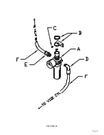
Page 67: ...Brass Street Elbow D 077780 Brass NPT Coupler E 077779 1 4 NPT Nipple F 045604 Complete Filter Regulator Lubricator G 045605 Mounting Brackets H 077738 90 Degree Fitting I 045609 Replacement Bowls J...

Page 68: ...Page 67 FIGURE 27...

Page 69: ...PTION A 046047 Cable End B 077744 Fitting 5 16 PL To 1 4 NPT C 077777 Plug 3 8 NPT D N A E 077740 Ninety Degree Elbow F 045650 Solenoid G 045655 Valve H 677728 Fitting 1 4 NPT To 1 4 PL J 045653 Compl...

Page 70: ...Page 69 FIGURE 28...

Page 71: ...Jam Nut E 026621 M 10 Tee Nut F 073766 Coolant Line G 046269 Hose Barb H 073450 M 4 x 16 SHCS I 076839 Mister Unit Optional Includes J K L J 676842 Hose Barb K 077926 Coolant Line L 060501 5 16 Air Li...

Page 72: ...Page 71 FIGURE 29...

Page 73: ...S C N A Fan D N A End Casting E 077325 Motor Bearing F N A Snap Ring G 076369 Key H 203210 M 10 SHCS I 077370 Key 6 x 4 x 32mm J N A Seal K N A Spacer Washer L N A Snap Ring 30mm Only M N A End Castin...

Page 74: ...Page 73 FIGURE 30...

Page 75: ...mer 150VA Replacement KM 24VDC Power Supply Motor Protect Switch 6 10 Amp Motor Protect Switch 1 6 Amp Page 74 D FNM 2 Grainger 4XC10 N A C REPLACEMENT PART Not exactly the same but will fit H 078285...

Page 76: ...Page 75 045345 Scotchman Inds PART NO FIGURE 31 A B D E F G C H I...

Page 77: ......

Page 78: ...Page 77 FIGURE 31B...

Page 79: ...460 Volt Coolant Pump F2 060160 575 Volt Coolant Pump G 049217 Leveling Pads G1 208024 M 24 Hex Nut H 073350 M 10 x 100 HHCS I 221010 M 6 x 16 SHCS J 203235 M 10 x 90 HHCS K 114020 Washer L 045475 Chi...

Page 80: ...Page 79 FIGURE 32...

Page 81: ...mp A1 060158 460 Volt Coolant Pump A2 060160 575 Volt Coolant Pump B 060152 Impeller C N A D 060151 Seal Kit E N A Bolt F N A Bolt G 060080 90 Degree Elbow H 060140 Coolant Line I 060095 Pump Cable J...

Page 82: ...Page 81 FIGURE 33...

Page 83: ......

Page 84: ...Page 83 FIGURE 34...

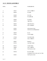
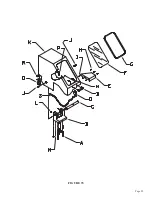
Page 85: ...ht Glass Seal H 201120 M 6 x 20 HHCS I 077157 M 6 Nylon Loc Nut J 229415 M 10 x 12 x 16 Shoulder Bolt K 045255 Hood L 077142 Grease Nipple M 077100 M 10 Dowel Pin N 073617 M 6 x 12 BHCS O 040012 Bumpe...

Page 86: ...Page 85 FIGURE 35...

Page 87: ...IPTION A 029243 Conveyor Assembly B 029244 Leg Assembly C 029245 Roller D 221210 M 10 x 25 HHCS E 076935 Optional Guide Assembly F 076942 Material Guide Base G 229225 M 10 x 70 Shoulder Bolt H 043003...

Page 88: ...Page 87 FIGURE 36...

Page 89: ...l 075757 5 GAL STAINLESS COOLANT 1 Qt 075753 1 QT AIRLINE LUBE ORM D 1 Gal 075759 1 GAL AIRLINE ORM D 1 Gal 075758 GEAR OIL HEAD 12 3 MAIN VISE REGULATOR ITEM PART A 078190 DESCRIPTION REGULATOR W GAU...

Page 90: ...Page 89 FIGURE 36...

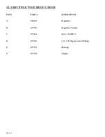
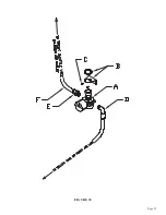
Page 91: ...Page 90 12 4 SHUTTLE VISE REGULATOR ITEM PART DESCRIPTION A 078190 Regulator B 677934 Regulator Mount C 077864 M 5 x 12 SHCS D 077746 1 4 x 90 Degree Swivel Fitting E 077721 Bushing F 077750 Nipple...

Page 92: ...Page 91 FIGURE 38...

Page 93: ...OID LOCATION SAW BASE 1 2 3 5 4 SAFETY VALVE SOLENOID DETAIL PARTS LIST DESCRIPTION PART QTY ITEM M6 X 35MM HHCS 201135 2 1 M6 HEX NUT 073206 2 2 3 8 90 MALE SWIVEL 077740 1 3 1169X5X6SZ ELBOW 90 MALE...

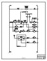
Page 94: ...Page 93 045345 Scotchman Inds PART NO 14 0 WIRING DIAGRAMS...

Page 95: ...045345 Scotchman Inds PART NO 1 3 Page 94...

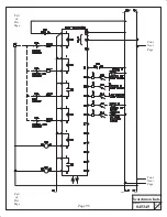
Page 96: ...Cont Next Page Cont Next Page Part of Prev Page Part of Prev Page Page 95 045345 Scotchman Inds PART NO 2 3...

Page 97: ...Cont Prev Page Cont Prev Page 045345 Scotchman Inds PART NO 3 3 Page 96...

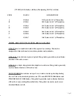
Page 98: ...50 074352 074354 DESCRIPTION 90 Tooth 12 1 2 315mm Dia 100 Tooth 12 1 2 315mm Dia 110 Tooth 12 1 2 315mm Dia 120 Tooth 12 1 2 315mm Dia 150 Tooth 12 1 2 315mm Dia 180 Tooth 12 1 2 315mm Dia 220 Tooth...

Page 99: ...s STYLE 2A is an alternate top bevel grind This grind is generally used on blades that have 220 teeth or more STYLE 3 is a triple chip grind with a high low tooth form This grind is generally used on...

Reviews: