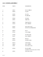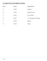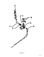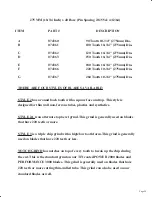
A
B
C
D
E
F
G
074360
074361
074362
074363
074365
074366
074367
90 Tooth 10-3/4" (275mm) Dia.
100 Tooth 10-3/4" (275mm) Dia.
120 Tooth 10-3/4" (275mm) Dia.
150 Tooth 10-3/4" (275mm) Dia.
180 Tooth 10-3/4" (275mm) Dia.
220 Tooth 10-3/4" (275mm) Dia.
260 Tooth 10-3/4" (275mm) Dia.
Page 98
THERE ARE FOUR STYLES OF BLADES AVAILABLE:
STYLE 2 has a round back tooth with a square face and top. This style is
designed for thin wall non-ferrous tubes, plastics and synthetics.
STYLE 2A is an alternate top bevel grind. This grind is generally used on blades
that have 220 teeth or more.
STYLE 3 is a triple chip grind with a high/low tooth form. This grind is generally
used on blades that have 220 teeth or less.
NOTCH GRIND has notches on top of every tooth to break up the chip during
the cut. This is the standard grind on our TiN coated POWER 2000 blades and
PERFORMANCE 3000 blades. This grind is generally used on blades that have
220 teeth or more cutting thin-walled tube. This grind can also be used on our
standard blades as well.
275 MM (10-3/4 Inch) x 40 Bore (Pin Spacing 2/8/55 & 4/12/64)
ITEM
PART #
DESCRIPTION
Summary of Contents for CPO-315-HFA-5HP
Page 8: ...Page 7 FIGURE 1...
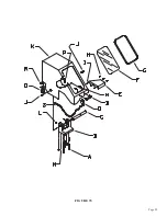
Page 10: ...Page 9 FIGURE 2...
Page 18: ...Page 17 THIS PAGE LEFT BLANK INTENTIONALLY...
Page 19: ...Page 18 6 2 BLADE INSTALLATION SEE FIGURE 4 BELOW FIGURE 4...
Page 23: ...Page 22 6 4 MATERIAL MAIN VISE SEE FIGURE 6 BELOW FIGURE 6...
Page 25: ...Page 24 FIGURE 7...
Page 27: ...Page 26 6 6 POWER DOWN FEED REFER TO FIGURE 8 BELOW FIGURE 8...
Page 30: ...Page 29 FIGURE 9...
Page 31: ...Page 30 6 9 COUNTER SET UP REFER TO FIGURE 10 BELOW FIGURE 10...
Page 37: ...Page 36 8 4 GEAR REPLACEMENT SAW HEAD REFER TO FIGURE 13 BELOW FIGURE 13...
Page 39: ...Page 38 8 5 SPINDLE REPLACEMENT MAIN VISE SEE FIGURE 14 BELOW FIGURE 14...
Page 41: ...Page 40 8 7 SHUTTLE VISE MAINTENANCE SEE FIGURE 15 BELOW FIGURE 15...
Page 46: ...Page 45 FIGURE 17...
Page 58: ......
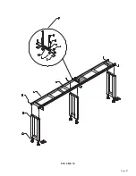
Page 62: ...Page 61 FIGURE 24...
Page 64: ...Page 63 FIGURE 25...
Page 66: ...Page 65 FIGURE 26...
Page 68: ...Page 67 FIGURE 27...
Page 70: ...Page 69 FIGURE 28...
Page 72: ...Page 71 FIGURE 29...
Page 74: ...Page 73 FIGURE 30...
Page 76: ...Page 75 045345 Scotchman Inds PART NO FIGURE 31 A B D E F G C H I...
Page 77: ......
Page 78: ...Page 77 FIGURE 31B...
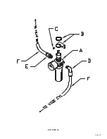
Page 80: ...Page 79 FIGURE 32...
Page 82: ...Page 81 FIGURE 33...
Page 83: ......
Page 84: ...Page 83 FIGURE 34...
Page 86: ...Page 85 FIGURE 35...
Page 88: ...Page 87 FIGURE 36...
Page 90: ...Page 89 FIGURE 36...
Page 92: ...Page 91 FIGURE 38...
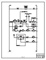
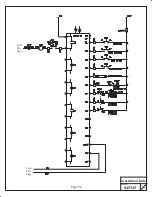
Page 94: ...Page 93 045345 Scotchman Inds PART NO 14 0 WIRING DIAGRAMS...
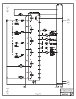
Page 95: ...045345 Scotchman Inds PART NO 1 3 Page 94...
Page 97: ...Cont Prev Page Cont Prev Page 045345 Scotchman Inds PART NO 3 3 Page 96...

