Page 15
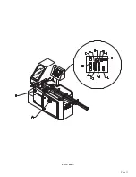
5.1F HEAD DOWN
This button is also used to set the overall stroke of the machine and to make manual cuts.
5.1G HITCH SELECTOR
This switch is used to select the number of hitches the shuttle vise makes before the saw makes a cut.
POSITION 1 is for parts from 0 to thirty inches in length.
POSITION 2 is for parts from thirty to sixty inches.
POSITION 3 is for parts from sixty to ninety inches.
5.1H CYCLE/START BUTTON
This button starts the machine cycle. The CYCLE/START button is used to make trim cuts and setup
cuts prior to starting the automatic operation. It is also used to start the automatic operation once all of
the test cuts are done.
5.1 I AUTOMATIC/MANUAL SWITCH
This switch must be in the MANUAL position to start the machine, to make trim cuts and to set the
product lengths. After the machine has been set up and sample cuts have been made, this switch is
moved to the AUTOMATIC position. Any time the saw is in the AUTOMATIC position, this switch can
be turned to the MANUAL position. When it is turned to the MANUAL position, the machine will
complete the cycle it’s on and stop when the head reaches the up position. The saw motor will continue to
run when this switch is used to stop the automatic operation of the machine. When this switch is in the
AUTOMATIC position and the machine runs out of product, the operator must reset the machine’s
operation. For instructions on changing bars of material, REFER TO SECTION 7.0. When this switch
is used to stop the automatic operation, you can start the automatic operation again by depressing the
TRIM/TEST SWITCH (J) and then, the CYCLE button (H). The machine will trim and cut one part.
You can then switch the AUTOMATIC/MANUAL SWITCH to the AUTOMATIC position and press the
cycle button again. The machine will continue with the automatic operation.
5.1J TRIM/TEST
This button is used to do first part cuts prior to running the machine in the automatic position. With the
AUTO/MANUAL switch in the MANUAL position, press the TRIM/TEST button (J) and then, press the
CYCLE button (H). The saw will trim, and then cut, one part and return to the up position.
Make whatever adjustments you need to and depress the CYCLE button (H) again and the saw will cut
one more test piece. After you are satisfied with all of the settings, place the AUTO/MANUAL switch (I)
in the AUTOMATIC position and press the CYCLE button again. The saw will start the automatic
operation.
Summary of Contents for CPO-315-HFA-NF
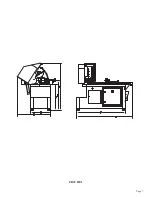
Page 8: ...Page 7 FIGURE 1...
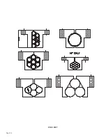
Page 10: ...Page 9 FIGURE 2...
Page 14: ...Page 13 FIGURE 3...
Page 18: ...Page 17 THIS PAGE LEFT BLANK INTENTIONALLY...
Page 22: ...Page 21 THIS PAGE LEFT BLANK INTENTIONALLY...
Page 23: ...Page 22 6 3 MATERIAL MAIN VISE SEE FIGURE 6 BELOW FIGURE 6...
Page 25: ...Page 24 FIGURE 7...
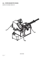
Page 27: ...Page 26 6 6 POWER DOWN FEED REFER TO FIGURE 8 BELOW FIGURE 8...
Page 30: ...Page 29 FIGURE 9...
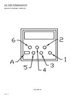
Page 31: ...Page 30 6 9 COUNTER SET UP REFER TO FIGURE 10 BELOW FIGURE 10...
Page 33: ...Page 32 7 0 MACHINE AUTOMATIC OPERATION SET UP REFER TO FIGURE 11 BELOW FIGURE 11...
Page 37: ...Page 36 8 4 SPINDLE SHAFT REPLACEMENT REFER TO FIGURE 13 BELOW FIGURE 13...
Page 39: ...Page 38 8 5 SPINDLE REPLACEMENT MAIN VISE SEE FIGURE 14 BELOW FIGURE 14...
Page 41: ...Page 40 8 7 SHUTTLE VISE MAINTENANCE SEE FIGURE 15 BELOW FIGURE 15...
Page 44: ...Page 43 FIGURE 16...
Page 50: ...Page 49 FIGURE 18...
Page 56: ......
Page 60: ...Page 59 FIGURE 23...
Page 62: ...Page 61 FIGURE 24...
Page 64: ...Page 63 FIGURE 25...
Page 66: ...Page 65 FIGURE 26...
Page 68: ...Page 67 FIGURE 27...
Page 70: ...Page 69 FIGURE 28...
Page 72: ...Page 71 FIGURE 29...
Page 75: ......
Page 76: ......
Page 78: ...Page 77 FIGURE 31...
Page 80: ...Page 79 FIGURE 32...
Page 82: ...Page 81 FIGURE 33...
Page 84: ...Page 83 FIGURE 34...
Page 86: ...Page 85 FIGURE 35...
Page 88: ...Page 87 FIGURE 36...
Page 90: ...Page 89 FIGURE 37...
Page 92: ...14 0 WIRING DIAGRAMS Page 91 045345 Scotchman Inds PART NO...
Page 93: ...3 5PB 1PL 045345 Scotchman Inds PART NO 1 3 Page 92 Ser s B1392HFANF0314 Up Part of Next Page...


