Page 23
The following are set-up and maintenance instructions for the material vise.
1.
Make sure that the filter/lubricating device (A) is full of oil. Use a quality (ISO 22) air line
lubricant designed for automatic oilers.
2.
Slide the shuttle valve (F) on the filter/lubricating device down to the closed position.
3.
Connect the air supply to the shuttle valve. Make sure that the vise is clear and that the head of
the saw is in the UP position.
4.
Slide the shuttle valve up to open the valve. Whenever the shuttle valve is closed, it bleeds the
air pressure out of the system automatically.
5.
Adjust the air pressure regulator (C). 90 PSI (6.2 BAR) is the minimum operating pressure. 130
PSI (9 BAR) is the maximum.
6.
The vise is activated by the top proximity switch on the saw head.
7.
The lubricating device (A) should release one drop of oil every 5 to 10 cycles. On top of the
lubricating device is a clear plastic dome with a small tube inside. The oil should drop out of the
tube. The lubricating device is adjusted by turning the knob (B) on the top of the lubricator.
8.
To add oil to the lubricating device, disconnect the air supply and remove the plastic bowl. The
bowl is threaded and is removed by turning the threaded collar (G). Fill the bowl
approximately 3/4 full of (ISO 22) air line oil designed for air lubricators and screw it back
onto the lubricator.
TO ADJUST THE VISE TO THE SIZE OF MATERIAL BEING CUT:
1.
Open the vise, using the positioning handle (E), place the material in the vise.
2.
Crank the vise closed to within approximately 1/8 of an inch (3mm) from the material. The
power vise has approximately 1/4 of an inch (6mm) of stroke. Proper clamping is very
important and special jaws may be required for some materials.
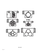
FOR EXAMPLES, REFER TO FIGURE 7 ON THE FOLLOWING PAGE.
Summary of Contents for CPO-315-HFA-NF
Page 8: ...Page 7 FIGURE 1...
Page 10: ...Page 9 FIGURE 2...
Page 14: ...Page 13 FIGURE 3...
Page 18: ...Page 17 THIS PAGE LEFT BLANK INTENTIONALLY...
Page 22: ...Page 21 THIS PAGE LEFT BLANK INTENTIONALLY...
Page 23: ...Page 22 6 3 MATERIAL MAIN VISE SEE FIGURE 6 BELOW FIGURE 6...
Page 25: ...Page 24 FIGURE 7...
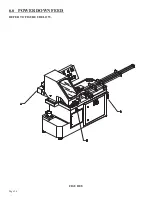
Page 27: ...Page 26 6 6 POWER DOWN FEED REFER TO FIGURE 8 BELOW FIGURE 8...
Page 30: ...Page 29 FIGURE 9...
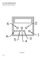
Page 31: ...Page 30 6 9 COUNTER SET UP REFER TO FIGURE 10 BELOW FIGURE 10...
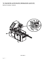
Page 33: ...Page 32 7 0 MACHINE AUTOMATIC OPERATION SET UP REFER TO FIGURE 11 BELOW FIGURE 11...
Page 37: ...Page 36 8 4 SPINDLE SHAFT REPLACEMENT REFER TO FIGURE 13 BELOW FIGURE 13...
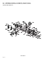
Page 39: ...Page 38 8 5 SPINDLE REPLACEMENT MAIN VISE SEE FIGURE 14 BELOW FIGURE 14...
Page 41: ...Page 40 8 7 SHUTTLE VISE MAINTENANCE SEE FIGURE 15 BELOW FIGURE 15...
Page 44: ...Page 43 FIGURE 16...
Page 50: ...Page 49 FIGURE 18...
Page 56: ......
Page 60: ...Page 59 FIGURE 23...
Page 62: ...Page 61 FIGURE 24...
Page 64: ...Page 63 FIGURE 25...
Page 66: ...Page 65 FIGURE 26...
Page 68: ...Page 67 FIGURE 27...
Page 70: ...Page 69 FIGURE 28...
Page 72: ...Page 71 FIGURE 29...
Page 75: ......
Page 76: ......
Page 78: ...Page 77 FIGURE 31...
Page 80: ...Page 79 FIGURE 32...
Page 82: ...Page 81 FIGURE 33...
Page 84: ...Page 83 FIGURE 34...
Page 86: ...Page 85 FIGURE 35...
Page 88: ...Page 87 FIGURE 36...
Page 90: ...Page 89 FIGURE 37...
Page 92: ...14 0 WIRING DIAGRAMS Page 91 045345 Scotchman Inds PART NO...
Page 93: ...3 5PB 1PL 045345 Scotchman Inds PART NO 1 3 Page 92 Ser s B1392HFANF0314 Up Part of Next Page...


