Page 25
6.5 SHUTTLE VISE AND CYLINDER
REFER TO FIGURE 6 ON PAGE 22.
CAUTION: ALWAYS DISCONNECT THE AIR SUPPLY BEFORE REMOVING THE
FILLER PLUG FROM THE RESERVOIR. IF THE FILLER PLUG IS REMOVED
WHILE THE MACHINE IS CONNECTED TO AIR PRESSURE, THE FLUID IN THE
TANK WILL BE PURGED THROUGH THE OPENING UNDER PRESSURE.
The fluid level in the reservoir should be 1-1/2 inches below the top of the reservoir when the
shuttle cylinder is completely extended, all the way to the left, up against the material main vise.
Do not add oil if the cylinder is in any other position. Over filling the reservoir will cause hydraulic
oil to be forced into the air system of the machine. Use a SAE 10W (ISO 32) non-foaming hydraulic
oil, such as Mobil DTE 10 or equivalent.
The following are set-up and maintenance instructions for the shuttle assembly.
1.
STEPS 1 THROUGH 8 are the same for the shuttle vise as they are for the material vise.
TO ADJUST THE VISE TO THE SIZE OF MATERIAL BEING CUT:
2.
Open the vise, using the positioning handle (D) and place the material in the vise.
3.
Crank the vise closed to within approximately 1/8 of an inch (3mm) from the material.
The power vise has approximately 1/4 of an inch (6mm) of stroke. Proper clamping is
very important and special jaws may be required for some materials. The speed of the
shuttle cylinder is controlled by the flow control valve (H) on the bottom of the reservoir.
Since the shuttle system is a positive stop type, feeding heavier materials too fast will
adversely affect the tolerance of the length of the part. The feed rate is preset and should
not need to be adjusted. If you do decide to adjust it, make the adjustments in small
increments.
Summary of Contents for CPO-315-HFA-NF
Page 8: ...Page 7 FIGURE 1...
Page 10: ...Page 9 FIGURE 2...
Page 14: ...Page 13 FIGURE 3...
Page 18: ...Page 17 THIS PAGE LEFT BLANK INTENTIONALLY...
Page 22: ...Page 21 THIS PAGE LEFT BLANK INTENTIONALLY...
Page 23: ...Page 22 6 3 MATERIAL MAIN VISE SEE FIGURE 6 BELOW FIGURE 6...
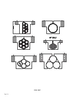
Page 25: ...Page 24 FIGURE 7...
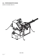
Page 27: ...Page 26 6 6 POWER DOWN FEED REFER TO FIGURE 8 BELOW FIGURE 8...
Page 30: ...Page 29 FIGURE 9...
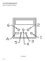
Page 31: ...Page 30 6 9 COUNTER SET UP REFER TO FIGURE 10 BELOW FIGURE 10...
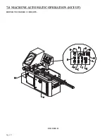
Page 33: ...Page 32 7 0 MACHINE AUTOMATIC OPERATION SET UP REFER TO FIGURE 11 BELOW FIGURE 11...
Page 37: ...Page 36 8 4 SPINDLE SHAFT REPLACEMENT REFER TO FIGURE 13 BELOW FIGURE 13...
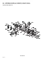
Page 39: ...Page 38 8 5 SPINDLE REPLACEMENT MAIN VISE SEE FIGURE 14 BELOW FIGURE 14...
Page 41: ...Page 40 8 7 SHUTTLE VISE MAINTENANCE SEE FIGURE 15 BELOW FIGURE 15...
Page 44: ...Page 43 FIGURE 16...
Page 50: ...Page 49 FIGURE 18...
Page 56: ......
Page 60: ...Page 59 FIGURE 23...
Page 62: ...Page 61 FIGURE 24...
Page 64: ...Page 63 FIGURE 25...
Page 66: ...Page 65 FIGURE 26...
Page 68: ...Page 67 FIGURE 27...
Page 70: ...Page 69 FIGURE 28...
Page 72: ...Page 71 FIGURE 29...
Page 75: ......
Page 76: ......
Page 78: ...Page 77 FIGURE 31...
Page 80: ...Page 79 FIGURE 32...
Page 82: ...Page 81 FIGURE 33...
Page 84: ...Page 83 FIGURE 34...
Page 86: ...Page 85 FIGURE 35...
Page 88: ...Page 87 FIGURE 36...
Page 90: ...Page 89 FIGURE 37...
Page 92: ...14 0 WIRING DIAGRAMS Page 91 045345 Scotchman Inds PART NO...
Page 93: ...3 5PB 1PL 045345 Scotchman Inds PART NO 1 3 Page 92 Ser s B1392HFANF0314 Up Part of Next Page...


