background image

Page 26

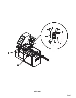
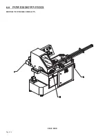
6.6   POWER DOWN FEED 

REFER TO FIGURE 8 BELOW. 

FIGURE 8

Summary of Contents for CPO-315-HFA-NF

Page 1: ...You have downloaded a manual for our MODEL CPO 315 HFA NF COLD SAW Please read the manual before operating this saw...

Page 2: ...www scotchman com PRINTED MAY 2021 SCOTCHMAN INDS 180 E US HWY 14 PO BOX 850 PHILIP SD 57567 Call 1 605 859 2542 MODEL CPO 315 HFA NF COLD SAW...

Page 3: ...6 0 MACHINE OPERATION 18 6 1 Blade Installation 18 6 2 Saw Capacities 21 6 3 Main Vise 22 6 4 Shuttle Vise 25 6 5 Power Down Feed 26 6 6 Material Clamping 28 6 7 Stroke Control Adjustment 28 6 8 Coun...

Page 4: ...mbly Power Down Feed Assembly 11 6A Power Down Feed Valves 11 6B Power Down Feed Air Controls 11 7 11 8 Air Valve Assembly Blade Guard Assembly 11 9 Motor Assembly 11 10 11 11 11 12 Electrical Unit Li...

Page 5: ...jaws for profiles and extrusions Having two spindle speeds enables the user to cut a wide range of materials 2 0 SAFETY PRECAUTIONS 1 The operators of this machine must be qualified and well trained i...

Page 6: ...e seller s option returns the defective goods freight and delivery prepaid to the seller which shall be the buyer s sole and exclusive remedy for defective goods Hydraulic and electrical components ar...

Page 7: ...IS MANUAL THOROUGHLY BEFORE OPERATING THIS MACHINE 4 1 PHYSICAL DIMENSIONS SEE FIGURE 1 ON THE FOLLOWING PAGE DIMENSIONS INCHES CM A HEIGHT 65 165 B FLOOR TO VISE 38 5 98 C BASE HEIGHT 35 89 D VISE OP...

Page 8: ...Page 7 FIGURE 1...

Page 9: ...he vises on the machine 4 Install the shuttle cylinder on the machine 5 We strongly recommend that the machine and any tracks be anchored to the floor The shipping brackets that hold the machine to th...

Page 10: ...Page 9 FIGURE 2...

Page 11: ...otor voltage rating Check the motor data tag for full load current requirements NOTE Machines that are wired for 208 Volt 3 Phase power require an additional step up transformer For additional informa...

Page 12: ...or the best results we recommend that it is used straight and not diluted The NF coolant reservoir has a capacity of 5 quarts 4 7 liters The pressure regulator for the mister should be set at 15 PSI 1...

Page 13: ...ot install a blade on the saw until after it has been powered and cycled several times Once the machine has been powered check the rotation of the spindle There is an arrow on the guard showing the pr...

Page 14: ...Page 13 FIGURE 3...

Page 15: ...ED AND TAGGED OR LOCKED OUT 5 1B MOTOR CONTROL SWITCH This switch is used to turn the motor on 5 1C POWER UP SWITCH This switch energizes the system for the rest of the control panel functions This sw...

Page 16: ...the head reaches the up position The saw motor will continue to run when this switch is used to stop the automatic operation of the machine When this switch is in the AUTOMATIC position and the machin...

Page 17: ...machine will run in the automatic position until the top row of the counter reaches the same number as the one you selected on the bottom row The machine will also quit the automatic operation if the...

Page 18: ...Page 17 THIS PAGE LEFT BLANK INTENTIONALLY...

Page 19: ...N SEE FIGURE 4 BELOW CAUTION THIS MACHINE IS DESIGNED TO USE CARBIDE TIPPED BLADES ONLY USE ONLY BLADES DESIGNED FOR THIS MACHINE DO NOT USE BLADES DESIGNED FOR THIS MACHINE ON ANY OTHER EQUIPMENT THE...

Page 20: ...holes in the spindle 6 Replace the blade flange C and start the bolt B into the spindle 7 Before locking the blade in position the back lash must be taken up To take up the back lash rotate the bottom...

Page 21: ...047200 HFA 90 ONLY 3 76 3 76 3 1 2 89 2 1 2 X 2 1 2 63 X 63 3 1 8 X 3 1 8 79 X 79 N A N A FERROUS FERROUS NF NF 2 1 2 X 2 1 2 63 X 63 2 1 2 X 2 1 2 63 X 63 3 1 8 X 3 1 8 79 X 79 2 1 2 X 2 1 2 63 X 63...

Page 22: ...Page 21 THIS PAGE LEFT BLANK INTENTIONALLY...

Page 23: ...Page 22 6 3 MATERIAL MAIN VISE SEE FIGURE 6 BELOW FIGURE 6...

Page 24: ...ating device A should release one drop of oil every 5 to 10 cycles On top of the lubricating device is a clear plastic dome with a small tube inside The oil should drop out of the tube The lubricating...

Page 25: ...Page 24 FIGURE 7...

Page 26: ...equivalent The following are set up and maintenance instructions for the shuttle assembly 1 STEPS 1 THROUGH 8 are the same for the shuttle vise as they are for the material vise TO ADJUST THE VISE TO...

Page 27: ...Page 26 6 6 POWER DOWN FEED REFER TO FIGURE 8 BELOW FIGURE 8...

Page 28: ...ate is adjusted using the flow control valve B The down feed rate should be set during the set up of an operation while the AUTOMATIC MANUAL switch is in the MANUAL position The setting of the down fe...

Page 29: ...he slot 3 Place a piece of the material you are going to cut in the saw vise and manually clamp it in a position so that the saw blade will not contact the material when the head comes down 4 Close th...

Page 30: ...Page 29 FIGURE 9...

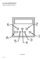
Page 31: ...Page 30 6 9 COUNTER SET UP REFER TO FIGURE 10 BELOW FIGURE 10...

Page 32: ...ton number 1 until Loop off appears on the display and then depress button number 6 6 The next option on the display is Relay nc or Relay no For this machine choose Relay no by pressing button number...

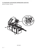
Page 33: ...Page 32 7 0 MACHINE AUTOMATIC OPERATION SET UP REFER TO FIGURE 11 BELOW FIGURE 11...

Page 34: ...ntrol valve N while it is making the first cut 10 Check the accuracy of the first part and make any adjustments required The fine adjustment knob O will change the length of the part by 1 5 thousandth...

Page 35: ...erature bearing grease daily Apply oil to the shuttle vise guide shafts daily Clean the chips out of the vise at least once a day more often if needed Apply penetrating oil to the spindle and guide pi...

Page 36: ...THE FLUID IN THE TANK WILL BE PURGED THROUGH THE OPENING UNDER PRESSURE 8 3 SCHEDULED MAINTENANCE A program of scheduled maintenance should be set up and documented according to your application and...

Page 37: ...Page 36 8 4 SPINDLE SHAFT REPLACEMENT REFER TO FIGURE 13 BELOW FIGURE 13...

Page 38: ...the saw The housing F fits snugly in the frame E and may have to be tapped out with a hammer 3 Gently tap two steel wedges opposite of each other between the housing F and the bearing retainer K 4 Pl...

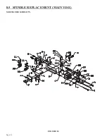
Page 39: ...Page 38 8 5 SPINDLE REPLACEMENT MAIN VISE SEE FIGURE 14 BELOW FIGURE 14...

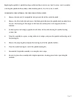
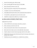
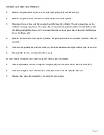
Page 40: ...e and reassemble the vise reversing the above steps 8 6 SEAL REPLACEMENT MAIN VISE SEE FIGURE 14 ON PAGE 38 1 Make sure that the power and air supply to the machine are both off 2 Remove the bolts A B...

Page 41: ...Page 40 8 7 SHUTTLE VISE MAINTENANCE SEE FIGURE 15 BELOW FIGURE 15...

Page 42: ...the lines simply push the air line into the fitting as far as it will go easily 4 Remove the four bolts Z from the cylinder end plate and remove the cylinder assembly from the machine 5 Slide the vis...

Page 43: ...nput side of the saw to support longer pieces of material is an available option for this saw The supply tracks can also be bolted end to end to supply longer tracks if needed SEE FIGURE 16 ON THE FOL...

Page 44: ...Page 43 FIGURE 16...

Page 45: ...ase correspond to the saw motor s voltage and phase B Disconnect the machine from the power source and check for any loose or disconnected wires C The supply lines to the machine must be of adequate s...

Page 46: ...being cut adheres itself to the sides of the saw blade When pick up is present you will notice a jerking or jumping motion in the saw head while cutting This is caused by the blade being pinched as i...

Page 47: ...any cracks or poor connections on the line it will not siphon the coolant out of the reservoir C Check the level of the coolant in the reservoir D Check the reservoir for contamination or sludge buil...

Page 48: ...should be activated anytime there is power to the machine and the E Stop is not activated I 2 is the input for the Shuttle Out limit switch It should only be activated when the shuttle vise is in the...

Page 49: ...al kit installation instructions REFER TO SECTIONS 8 6 8 7 C Loose connections in the air lines All of the air lines on this machine are the snap in connector type To remove the hose push in on the sl...

Page 50: ...Page 49 FIGURE 18...

Page 51: ...ng Housing G 077909 Needle Bearing H 077897 Snap Ring 33mm I 075077 Bearing J 075075 Seal K 077896 Seal Flange L 077894 Spindle Shaft M 077626 Saw Flange N 077908 M 10 Bolt Left Hand O 046094 Wire Cli...

Page 52: ...Page 51 GG 073920 M 10 Dowel Pin Included in M 077929 Spindle Assembly Includes C D F G H I J K L N P BB FIGURE 19...

Page 53: ...down Plate N 221210 M 10 x 25 SHCS O 045304 Vise Side Plate P 221412 M 16 x 35 SHCS Q 045307 Upper Wear Plate R 230005 M 6 x 12 FSHCS S 077100 M 10 Dowel Pin T 045303 End Plate U 201620 M 16 x 55 HHCS...

Page 54: ...JJ 219047 M 10 x 12 Set Screw KK 077798 Vise Jaws LL 203212 M 10 x 30 HHCS MM 045224 Clevis Wear Plate NN 210012 M 10 Jam Nut OO 060270 End Cap PP 114020 M 10 Washer 045300 Complete Vise Assembly FIG...

Page 55: ...045199 077798 203212 045602 210012 046667 DESCRIPTION 5 8 x 11 Jam Nut Boss Cylinder Body Cylinder Rebuild Kit Shuttle Vise Cylinder Mounting Plate Fitting Detent Block Detent Ball M 10 Set Screw M 8...

Page 56: ......

Page 57: ...ter 3 8 NPT Filler Plug 3 8 NPT Nipple Flow Control Valve 1168 x 1 2 Male Connector Line Cylinder 1 2 Line Valve 5 16 1 4 NPT x 169 Plastic M 10 x 25 SHCS Reed Switch P8S GRFAX 11699 x 3 8 90 Degree E...

Page 58: ...Page 57 GG 230207 M 20 FSHCS HH 218000 M 8 x 8 Set Screw II 045254 Roller JJ 221212 M 10 x 30 SHCS KK 045259 Roller Block FIGURE 22...

Page 59: ...206 Adjustment Collar C 016063 1 1 2 Snap Ring D 046652 Detent Ball E 045602 Detent Spring F 045204 Sliding Stop G 204225 M 10 x 80 HHCS H 221212 M 10 SHCS I 045259 Roller Block J 045254 Roller K 1140...

Page 60: ...Page 59 FIGURE 23...

Page 61: ...servoir C 077715 Pivot Belt D 045232 Cylinder Bracket E N A 3 8 Nylon Lock Nut Included in A F 041015 Flow Control Valve G 221212 M 10 x 30 SHCS H 047100 Upper Bracket Assembly I 221210 M 10 x 25 SHCS...

Page 62: ...Page 61 FIGURE 24...

Page 63: ...077777 3 8 NPT Plug D 045054 1 2 x 90 Degree Swivel x 169 PL E 077536 Check Valve Auto Saws Only F 045042 Return Line Fitting G H I MVK6 Mounting Kit J 047535 Flow Control Valve K 045054 1 4 NPT x 5 1...

Page 64: ...Page 63 FIGURE 25...

Page 65: ...Brass Street Elbow D 077780 Brass NPT Coupler E 077779 1 4 NPT Nipple F 045604 Complete Filter Regulator Lubricator G 045605 Mounting Brackets H 077738 90 Degree Fitting I 045609 Replacement Bowls J...

Page 66: ...Page 65 FIGURE 26...

Page 67: ...7 Plug 3 8 NPT E 077740 90 Degree Elbow F 045650 Solenoid G 045655 Valve H 677728 Fitting 1 4 NPT to 1 4 PL I 077779 1 4 Pipe Nipple J 077741 1 4 Male SW x 169 PL K 077750 1 8 Pipe Nipple L 077721 Bus...

Page 68: ...Page 67 FIGURE 27...

Page 69: ...ARD ASSEMBLY ITEM PART DESCRIPTION A 045267 Guard Shell B 677901 M 10 x 55 SHCS I 076839 Mister Unit J 676842 Hose Barb Elbow K 077926 Coolant Line L 060501 Air Line M 676844 Fitting N 073095 M 4 Wash...

Page 70: ...Page 69 FIGURE 28...

Page 71: ...ng 25mm Bore DA 077381 End Casting 30mm Bore E 075049 Motor Bearing 6205Z 25mm EA 077325 Motor Bearing 6206 30mm F 077191 Snap Ring G 076369 Key H 073326 M 8 x 30 SHCS I 077370 Key 6 x 4 x 32mm J 0773...

Page 72: ...Page 71 FIGURE 29...

Page 73: ...itch KM AFR Primary Fuse 1 2 AMP Transformer 150VA Replacement KM 24VDC Power Supply Motor Protect Switch 6 10 Amp Motor Protect Switch 1 6 Amp Page 72 D FNM 2 Grainger 4XC10 N A C REPLACEMENT PART No...

Page 74: ...ADDED THESE WIRES STARTING WITH SER B1418HFANF0616 FIGURE 30A Page 73 045345 Scotchman Inds PART NO A B D C E F G H...

Page 75: ......

Page 76: ......

Page 77: ...Screen For Mister G 049217 Leveling Pads G1 208024 M 24 Hex Nut H 073350 M 10 x 100 HHCS J N A K N A M 4 x 12 SHCS L 045470 Chip And Parts Chute M 221120 M 8 x 25 SHCS N 045052 Chip Bucket O 046018 H...

Page 78: ...Page 77 FIGURE 31...

Page 79: ...677728 1 4 NPT x 1 4 Hose B 677745 1 4 Brass Tee C 077721 1 4 To 1 8 NPT Reducer D 077750 1 8 x 2 1 2 Pipe Nipple E 077930 Mister Regulator F 677933 Mister Reservoir G 077779 1 4 Brass Nipple H 07774...

Page 80: ...Page 79 FIGURE 32...

Page 81: ...210 221120 DESCRIPTION Stroke Adjustment Plate Stroke Control Stand Stop Block Sensor Weldment Stop Guide M 4 x 12 SHCS M 10 x 30 HHCS 3 8 Hard Washer M 10 x 35 SHCS M 10 x 25 SHCS M 8 x 25 SHCS Page...

Page 82: ...Page 81 FIGURE 33...

Page 83: ...20 M 6 x 20 HHCS I 077157 M 6 Hex Nut J 229415 M 10 x 12 x 16 Shoulder Bolt K 047151 Hood L 077142 Grease Nipple M 077100 M 10 Dowel Pin N 073617 M 6 x 12 BHCS O 040012 Bumpers P 047110 Interlock Swit...

Page 84: ...Page 83 FIGURE 34...

Page 85: ...IPTION A 029243 Conveyor Assembly B 029244 Leg Assembly C 029245 Roller D 221210 M 10 x 25 HHCS E 076935 Optional Guide Assembly F 076942 Material Guide Base G 229225 M 10 x 70 Shoulder Bolt H 043003...

Page 86: ...Page 85 FIGURE 35...

Page 87: ...Lubricant do not dilute 55 Gal 075761 55 GAL SYNCON 2 do not dilute 12 3 VISE REGULATOR ITEM PART A 078190 DESCRIPTION REGULATOR W GAUGE B 677934 NF FRL WALL MOUNT BRACKET C 077864 M5 X 12 DIN912 SHC...

Page 88: ...Page 87 FIGURE 36...

Page 89: ...Page 88 12 4 SHUTTLE VISE REGULATOR ITEM PART DESCRIPTION A 078190 Regulator B 677934 Regulator Mount C 077864 M 5 x 12 SHCS D 077746 1 4 x 90 Swivel Fittings E 077721 Bushing F 077750 1 4 Nipple...

Page 90: ...Page 89 FIGURE 37...

Page 91: ...OID LOCATION SAW BASE 1 2 3 5 4 SAFETY VALVE SOLENOID DETAIL PARTS LIST DESCRIPTION PART QTY ITEM M6 X 35MM HHCS 201135 2 1 M6 HEX NUT 073206 2 2 3 8 90 MALE SWIVEL 077740 1 3 1169X5X6SZ ELBOW 90 MALE...

Page 92: ...14 0 WIRING DIAGRAMS Page 91 045345 Scotchman Inds PART NO...

Page 93: ...3 5PB 1PL 045345 Scotchman Inds PART NO 1 3 Page 92 Ser s B1392HFANF0314 Up Part of Next Page...

Page 94: ...Cont Next Page Cont Next Page Page 93 045345 Scotchman Inds PART NO 2 3 Ser s B1392HFANF0314 Up Part of Prev Page Part of Prev Page...
Page 95: ...Cont Prev Page Cont Prev Page 045345 Scotchman Inds PART NO 3 3 Page 94 Ser s B1392HFANF0314 Up...

Reviews: