Page 28
6.7 MATERIAL CLAMPING
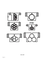
All work pieces must be clamped securely in the vise. Any slippage of the material can result in broken
or damaged blades. The material should be clamped so that the contact surface between the material
and the blade is as small as possible. For this reason, when cutting flat stock material, we recommend
standing it up and cutting it through the thinnest section, whenever possible. We also recommend cutting
square tubing through the diagonal section and angle iron with the web up. Some thin walled round
sections and profiles will require special jaws to hold them.
FOR EXAMPLES, SEE FIGURE 7 ON PAGE 24.
6.8 STROKE CONTROL ADJUSTMENT
SEE FIGURE 9 ON THE FOLLOWING PAGE. TO ADJUST THE UP AND DOWN STROKE OF THE
SAW HEAD, USE THE FOLLOWING STEPS:
1.
With the machine’s power off, raise the hood of the saw.
2.
Using a 17mm wrench, loosen the bolt (A) on the lower stroke control (B) and let the stroke
control rest at the bottom of the slot.
3.
Place a piece of the material you are going to cut in the saw vise and manually clamp it in a
position so that the saw blade will not contact the material when the head comes down.
4.
Close the hood. The saw will not run with the hood open.
5.
Make sure that the motor switch (D) is in the 0 position so that the saw blade does not turn while
performing this set up.
6.
Power the saw and press the HEAD DOWN button (E).
7.
When the blade has passed the material in the vise by approximately 1/8 of an inch (3mm), stop
the head movement by turning off the flow control valve (F) and turn off the air pressure by
sliding the shuttle valve (G) down.
8.
Turn the power off and raise the hood. Bring the lower stroke control (B) up to the head stop and
lock it in place.
9.
Bring the upper stroke control (C) down to the head stop and lock it in place.
10.
Turn the air back on by moving the shuttle valve (G) up and open the flow control valve (F) one
turn.
11.
Loosen the bolt (A) on the upper stroke control (C) and allow the head to move slowly up until the
blade is approximately 1/8 of an inch (3mm) above the material in the vise. Tighten the bolt in the
upper stroke control.
Summary of Contents for CPO-315-HFA-NF
Page 8: ...Page 7 FIGURE 1...
Page 10: ...Page 9 FIGURE 2...
Page 14: ...Page 13 FIGURE 3...
Page 18: ...Page 17 THIS PAGE LEFT BLANK INTENTIONALLY...
Page 22: ...Page 21 THIS PAGE LEFT BLANK INTENTIONALLY...
Page 23: ...Page 22 6 3 MATERIAL MAIN VISE SEE FIGURE 6 BELOW FIGURE 6...
Page 25: ...Page 24 FIGURE 7...
Page 27: ...Page 26 6 6 POWER DOWN FEED REFER TO FIGURE 8 BELOW FIGURE 8...
Page 30: ...Page 29 FIGURE 9...
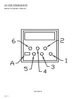
Page 31: ...Page 30 6 9 COUNTER SET UP REFER TO FIGURE 10 BELOW FIGURE 10...
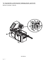
Page 33: ...Page 32 7 0 MACHINE AUTOMATIC OPERATION SET UP REFER TO FIGURE 11 BELOW FIGURE 11...
Page 37: ...Page 36 8 4 SPINDLE SHAFT REPLACEMENT REFER TO FIGURE 13 BELOW FIGURE 13...
Page 39: ...Page 38 8 5 SPINDLE REPLACEMENT MAIN VISE SEE FIGURE 14 BELOW FIGURE 14...
Page 41: ...Page 40 8 7 SHUTTLE VISE MAINTENANCE SEE FIGURE 15 BELOW FIGURE 15...
Page 44: ...Page 43 FIGURE 16...
Page 50: ...Page 49 FIGURE 18...
Page 56: ......
Page 60: ...Page 59 FIGURE 23...
Page 62: ...Page 61 FIGURE 24...
Page 64: ...Page 63 FIGURE 25...
Page 66: ...Page 65 FIGURE 26...
Page 68: ...Page 67 FIGURE 27...
Page 70: ...Page 69 FIGURE 28...
Page 72: ...Page 71 FIGURE 29...
Page 75: ......
Page 76: ......
Page 78: ...Page 77 FIGURE 31...
Page 80: ...Page 79 FIGURE 32...
Page 82: ...Page 81 FIGURE 33...
Page 84: ...Page 83 FIGURE 34...
Page 86: ...Page 85 FIGURE 35...
Page 88: ...Page 87 FIGURE 36...
Page 90: ...Page 89 FIGURE 37...
Page 92: ...14 0 WIRING DIAGRAMS Page 91 045345 Scotchman Inds PART NO...
Page 93: ...3 5PB 1PL 045345 Scotchman Inds PART NO 1 3 Page 92 Ser s B1392HFANF0314 Up Part of Next Page...

