Page 35
8.2 CUTTING OILS AND LUBRICANTS
SECTION 12.2 lists Scotchman's part numbers for cutting oils and lubricants. Using high
quality lubricants and oils will greatly increase the life of this equipment.
We recommend using only our P/N 075760 - SYNCON-2 straight - not diluted.
For the power down feed, use a SAE 10W (ISO 32) non-foaming hydraulic oil, such as Mobil
DTE 10 or equivalent in the reservoir. For the air lubricators, use a quality (ISO 22) air line
lubricant designed for automatic oilers.
CAUTION: ALWAYS DISCONNECT THE AIR SUPPLY BEFORE REMOVING THE
FILLER PLUG FROM THE RESERVOIR. IF THE FILLER PLUG IS REMOVED
WHILE THE MACHINE IS CONNECTED TO AIR PRESSURE, THE FLUID IN THE
TANK WILL BE PURGED THROUGH THE OPENING UNDER PRESSURE.
8.3 SCHEDULED MAINTENANCE
A program of scheduled maintenance should be set up and documented according to your application
and the frequency you use the machine. The following is a list of some important things that should be
included in a scheduled maintenance program.
1.
EVERY 250 HOURS OR 3 MONTHS:
Drain the coolant reservoir and flush it out. Refill the coolant reservoir with new coolant.
Check hydraulic fluid level in the power down feed and the shuttle cylinder reservoirs.
2.
EVERY 750 HOURS OR 6 MONTHS:
Check the condition of the pivot pins on the head and on the guard. Check the complete saw for
loose connections in the electrical and air systems.
Since every application is different, each user must design and implement a scheduled maintenance
program that fits his applications.
Summary of Contents for CPO-315-HFA-NF
Page 8: ...Page 7 FIGURE 1...
Page 10: ...Page 9 FIGURE 2...
Page 14: ...Page 13 FIGURE 3...
Page 18: ...Page 17 THIS PAGE LEFT BLANK INTENTIONALLY...
Page 22: ...Page 21 THIS PAGE LEFT BLANK INTENTIONALLY...
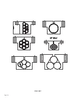
Page 23: ...Page 22 6 3 MATERIAL MAIN VISE SEE FIGURE 6 BELOW FIGURE 6...
Page 25: ...Page 24 FIGURE 7...
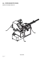
Page 27: ...Page 26 6 6 POWER DOWN FEED REFER TO FIGURE 8 BELOW FIGURE 8...
Page 30: ...Page 29 FIGURE 9...
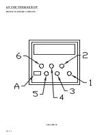
Page 31: ...Page 30 6 9 COUNTER SET UP REFER TO FIGURE 10 BELOW FIGURE 10...
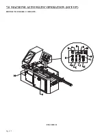
Page 33: ...Page 32 7 0 MACHINE AUTOMATIC OPERATION SET UP REFER TO FIGURE 11 BELOW FIGURE 11...
Page 37: ...Page 36 8 4 SPINDLE SHAFT REPLACEMENT REFER TO FIGURE 13 BELOW FIGURE 13...
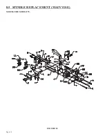
Page 39: ...Page 38 8 5 SPINDLE REPLACEMENT MAIN VISE SEE FIGURE 14 BELOW FIGURE 14...
Page 41: ...Page 40 8 7 SHUTTLE VISE MAINTENANCE SEE FIGURE 15 BELOW FIGURE 15...
Page 44: ...Page 43 FIGURE 16...
Page 50: ...Page 49 FIGURE 18...
Page 56: ......
Page 60: ...Page 59 FIGURE 23...
Page 62: ...Page 61 FIGURE 24...
Page 64: ...Page 63 FIGURE 25...
Page 66: ...Page 65 FIGURE 26...
Page 68: ...Page 67 FIGURE 27...
Page 70: ...Page 69 FIGURE 28...
Page 72: ...Page 71 FIGURE 29...
Page 75: ......
Page 76: ......
Page 78: ...Page 77 FIGURE 31...
Page 80: ...Page 79 FIGURE 32...
Page 82: ...Page 81 FIGURE 33...
Page 84: ...Page 83 FIGURE 34...
Page 86: ...Page 85 FIGURE 35...
Page 88: ...Page 87 FIGURE 36...
Page 90: ...Page 89 FIGURE 37...
Page 92: ...14 0 WIRING DIAGRAMS Page 91 045345 Scotchman Inds PART NO...
Page 93: ...3 5PB 1PL 045345 Scotchman Inds PART NO 1 3 Page 92 Ser s B1392HFANF0314 Up Part of Next Page...


