Page 39
1.
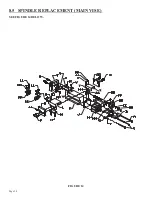
Disconnect the machine’s power and the air supply.
2.
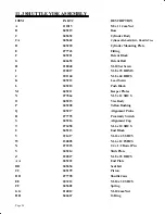
Remove the spindle shield (XX) and the spring (Y) and ball (HH).
3.
Remove the bolts (A & B) and the retainer (D).
4.
Remove the clevis pin (F) and remove the clevis (E) and the forks (CC).
5.
The spindle can now be removed from the machine.
6.
If the spindle is locked up in the machine, remove the bolts (II) and the side plate (GG).
7.
The vise block (L) and the spindle can now be removed as one piece.
8.
Install the new spindle and reassemble the vise, reversing the above steps.
8.6 SEAL REPLACEMENT (MAIN VISE)
SEE FIGURE 14 ON PAGE 38.
1.
Make sure that the power and air supply to the machine are both off.
2.
Remove the bolts (A & B) and the retainer (D).
3.
Remove the clevis pin (F) and the cylinder clevis (E) and the forks (CC).
4.
Remove the two lower bolts (C) and remove the cylinder (H) from the machine.
5.
Place the cylinder in a vise and remove the snap ring from the front of the cylinder.
6.
Pull the cylinder apart and remove all of the old seals. Check the end casting, cylinder tube and
piston for nicks or scratches.
7.
Install the new seals and reassemble the vise, reversing the above procedures.
Summary of Contents for CPO-315-HFA-NF
Page 8: ...Page 7 FIGURE 1...
Page 10: ...Page 9 FIGURE 2...
Page 14: ...Page 13 FIGURE 3...
Page 18: ...Page 17 THIS PAGE LEFT BLANK INTENTIONALLY...
Page 22: ...Page 21 THIS PAGE LEFT BLANK INTENTIONALLY...
Page 23: ...Page 22 6 3 MATERIAL MAIN VISE SEE FIGURE 6 BELOW FIGURE 6...
Page 25: ...Page 24 FIGURE 7...
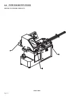
Page 27: ...Page 26 6 6 POWER DOWN FEED REFER TO FIGURE 8 BELOW FIGURE 8...
Page 30: ...Page 29 FIGURE 9...
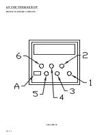
Page 31: ...Page 30 6 9 COUNTER SET UP REFER TO FIGURE 10 BELOW FIGURE 10...
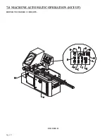
Page 33: ...Page 32 7 0 MACHINE AUTOMATIC OPERATION SET UP REFER TO FIGURE 11 BELOW FIGURE 11...
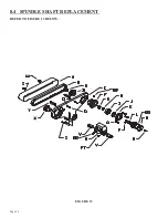
Page 37: ...Page 36 8 4 SPINDLE SHAFT REPLACEMENT REFER TO FIGURE 13 BELOW FIGURE 13...
Page 39: ...Page 38 8 5 SPINDLE REPLACEMENT MAIN VISE SEE FIGURE 14 BELOW FIGURE 14...
Page 41: ...Page 40 8 7 SHUTTLE VISE MAINTENANCE SEE FIGURE 15 BELOW FIGURE 15...
Page 44: ...Page 43 FIGURE 16...
Page 50: ...Page 49 FIGURE 18...
Page 56: ......
Page 60: ...Page 59 FIGURE 23...
Page 62: ...Page 61 FIGURE 24...
Page 64: ...Page 63 FIGURE 25...
Page 66: ...Page 65 FIGURE 26...
Page 68: ...Page 67 FIGURE 27...
Page 70: ...Page 69 FIGURE 28...
Page 72: ...Page 71 FIGURE 29...
Page 75: ......
Page 76: ......
Page 78: ...Page 77 FIGURE 31...
Page 80: ...Page 79 FIGURE 32...
Page 82: ...Page 81 FIGURE 33...
Page 84: ...Page 83 FIGURE 34...
Page 86: ...Page 85 FIGURE 35...
Page 88: ...Page 87 FIGURE 36...
Page 90: ...Page 89 FIGURE 37...
Page 92: ...14 0 WIRING DIAGRAMS Page 91 045345 Scotchman Inds PART NO...
Page 93: ...3 5PB 1PL 045345 Scotchman Inds PART NO 1 3 Page 92 Ser s B1392HFANF0314 Up Part of Next Page...


