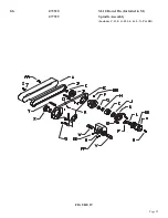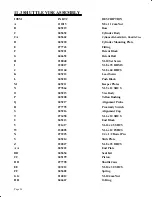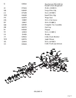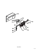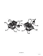
11.3 SHUTTLE VISE ASSEMBLY
ITEM
A
B
C
CA
D
E
F
G
H
I
J
K
L
M
N
O
P
Q
R
S
T
U
V
W
X
Y
Z
AA
BB
CC
DD
EE
FF
GG
HH
Page 54
PART #
111015
045219
045652
045662
045220
077743
045221
046652
218048
220027
201160
045212
045210
045211
077864
045215
045208
045217
077795
045216
073458
045213
221417
230005
073925
045214
220027
045222
045654
045199
077798
203212
045602
210012
046667
DESCRIPTION
5/8 x 11 Jam Nut
Boss
Cylinder Body
Cylinder Rebuild Kit - Shuttle Vise
Cylinder Mounting Plate
Fitting
Detent Block
Detent Ball
M-10 Set Screw
M-8 x 35 RHMS
M-8 x 60 HHCS
Lead Screw
Push Block
Keeper Plates
M-5 x 12 SHCS
Vise Body
Teflon Bushing
Alignment Probe
Proximity Switch
Alignment Cap
M-6 x 10 SHCS
End Block
M-16 x 45 SHCS
M-6 x 12 FSHCS
1/4 x 1/2 Dowel Pin
Slide Plate
M-8 x 35 BHCS
End Plate
Seal Kit
Piston
Shuttle Jaws
M-10 x 30 SHCS
Spring
M-10 Jam Nut
O-Ring
Summary of Contents for CPO-315-HFA-NF
Page 8: ...Page 7 FIGURE 1...
Page 10: ...Page 9 FIGURE 2...
Page 14: ...Page 13 FIGURE 3...
Page 18: ...Page 17 THIS PAGE LEFT BLANK INTENTIONALLY...
Page 22: ...Page 21 THIS PAGE LEFT BLANK INTENTIONALLY...
Page 23: ...Page 22 6 3 MATERIAL MAIN VISE SEE FIGURE 6 BELOW FIGURE 6...
Page 25: ...Page 24 FIGURE 7...
Page 27: ...Page 26 6 6 POWER DOWN FEED REFER TO FIGURE 8 BELOW FIGURE 8...
Page 30: ...Page 29 FIGURE 9...
Page 31: ...Page 30 6 9 COUNTER SET UP REFER TO FIGURE 10 BELOW FIGURE 10...
Page 33: ...Page 32 7 0 MACHINE AUTOMATIC OPERATION SET UP REFER TO FIGURE 11 BELOW FIGURE 11...
Page 37: ...Page 36 8 4 SPINDLE SHAFT REPLACEMENT REFER TO FIGURE 13 BELOW FIGURE 13...
Page 39: ...Page 38 8 5 SPINDLE REPLACEMENT MAIN VISE SEE FIGURE 14 BELOW FIGURE 14...
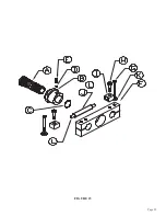
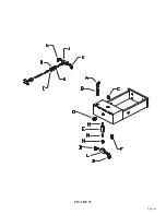
Page 41: ...Page 40 8 7 SHUTTLE VISE MAINTENANCE SEE FIGURE 15 BELOW FIGURE 15...
Page 44: ...Page 43 FIGURE 16...
Page 50: ...Page 49 FIGURE 18...
Page 56: ......
Page 60: ...Page 59 FIGURE 23...
Page 62: ...Page 61 FIGURE 24...
Page 64: ...Page 63 FIGURE 25...
Page 66: ...Page 65 FIGURE 26...
Page 68: ...Page 67 FIGURE 27...
Page 70: ...Page 69 FIGURE 28...
Page 72: ...Page 71 FIGURE 29...
Page 75: ......
Page 76: ......
Page 78: ...Page 77 FIGURE 31...
Page 80: ...Page 79 FIGURE 32...
Page 82: ...Page 81 FIGURE 33...
Page 84: ...Page 83 FIGURE 34...
Page 86: ...Page 85 FIGURE 35...
Page 88: ...Page 87 FIGURE 36...
Page 90: ...Page 89 FIGURE 37...
Page 92: ...14 0 WIRING DIAGRAMS Page 91 045345 Scotchman Inds PART NO...
Page 93: ...3 5PB 1PL 045345 Scotchman Inds PART NO 1 3 Page 92 Ser s B1392HFANF0314 Up Part of Next Page...


