background image

Page 16

5.1 A   MAIN POWER SWITCH 

This is the main power disconnect switch for the machine and it should be locked or tagged in the OFF 

position any time maintenance or service work is being performed. Maintenance or service work on the 

electrical controls must be performed by qualified personnel. This switch must be in the ON position 

to operate any of the other control panel functions. The control panel will light up on the home screen 

when the power switch (A) is on. With the hood switch open, cycle (D) stopped will appear on the 

control panel screen. Scroll across the top of the screen, close the hood and push to continue. When the 

E-Stop button (B) is pushed, the emergency stop will scroll across the top of the control panel screen. 

Turn the E-Stop clockwise to re-set it.

CAUTION: THIS SWITCH DOES NOT DISCONNECT THE AIR SUPPLY TO THE 

MACHINE. ANY TIME MAINTENANCE OR SERVICE WORK IS PERFORMED ON THE 

MACHINE, THE AIR SUPPLY MUST ALSO BE DISCONNECTED AND TAGGED OR 

LOCKED OUT. 

FIGURE 5

Summary of Contents for CPO-315-RFA-NF

Page 1: ...You have downloaded a manual for our MODEL CPO 315 RFA NF COLD SAW Please read the manual before operating this saw ...

Page 2: ...www scotchman com SCOTCHMAN INDS 180 E US HWY 14 PO BOX 850 PHILIP SD 57567 Call 1 605 859 2542 MODEL CPO 315 RFA NF COLD SAW S N B2053RFA0522 and up PRINTED SEPTEMBER 2022 ...

Page 3: ...Cut Profiles 5 1G Manual Operation Menu 18 5 1H Customer Calibration Set Up 19 5 1I Desired Length Screen 20 5 1J Factory Set Up Screen 21 5 1K Model Serial Number Menu 22 5 1L Maintenance Menu 23 5 1M Timer Screen 24 5 1N PLC Maintenance Screen 25 5 1O Hood Open Screen 26 5 1P Batch Complete 5 1Q Feed Failure Screen 27 5 1R Load Fault Screen 27 5 1S Cut Fail Screen 28 5 1T Alarms History Menu 28 ...

Page 4: ...acement Main Vise 48 8 6 Seal Replacement Main Vise 49 9 0 OPTIONAL EQUIPMENT 50 9 1 Special Vise Jaws and Guides 50 9 2 Optional Discharge Lengths 50 9 3 Digital Readout 50 9 4 Overturn Device 50 9 5 Vise Regulator 50 10 0 TROUBLE SHOOTING GUIDE 51 10 1 Electrical Trouble Shooting 51 10 2 Breakage or Excessive Dulling of Blades 52 10 3 Coolant System 53 10 4 54 Pneumatic System 11 0 PARTS LISTS 5...

Page 5: ...2 11 12 Air Valve Assembly 94 11 13 Blade Guard Assembly 11 14 Motor Assembly 98 11 15 Electrical Unit Line Circuit 11 16 Base Assembly 102 11 17 Mist Coolant System 104 Stroke Control Assembly Hood Assembly 12 0 OPTIONAL EQUIPMENT PARTS LISTS 106 12 1 Cutting Coolants and Lubricants 106 12 2 Digital Readout 107 12 3 Overturn Device 108 12 4 Vise Regulator 110 12 5 90 120 Discharge Table Assemblie...

Page 6: ...ns with varying cross section thicknesses To achieve the best results from this machine choose the proper spindle speed Proper material clamping and a good quality coolant are also important We recommend our P N 075760 coolant SYNCON 2 straight and not diluted Cold sawing has several advantages over band saws and abrasive saws Besides the mill quality cut cold saws have the ability to generate fas...

Page 7: ...e must be grounded in accordance with the National Electric Code 8 Disconnect the machine from the power source before performing maintenance or changing blades 9 Strictly comply with all of the warning labels and decals on the machine Never remove any of the labels Replace worn or damaged labels promptly 10 Practice good housekeeping Keep the area around the machine clean and dry Do not obstruct ...

Page 8: ...odified in any way or subjected to abusive or abnormal use inadequate maintenance or lubrication or subjected to use beyond the seller s recommended capacities and specifications In no event shall seller be liable for labor costs expended on such goods or consequential damages Seller shall not be liable to purchaser or any other person for loss or damage directly or indirectly arising from the use...

Page 9: ...YSICAL DIMENSIONS SEE FIGURE 1 ON THE FOLLOWING PAGE DIMENSIONS INCHES CM A HEIGHT 67 170 B FLOOR TO VISE 38 5 98 C BASE HEIGHT 35 89 D VISE OPENING 3 5 8 9 2 E VISE DEPTH 2 1 4 5 7 F BASE WIDTH 61 155 G BASE DEPTH 25 64 H OVERALL WIDTH 384 975 I DEPTH 46 112 K WIDTH OF SUPPLY TABLE 258 655 L WIDTH OF DISCHARGE ASSEMBLY 65 165 WEIGHT 2 170 LB 986 KG OPTIONAL BUNDLE LOADER 1 660 LB 755 KG ...

Page 10: ...Page 9 FIGURE 1 A D E B C G I L F K ...

Page 11: ... level it and the discharge track using the leveling pads For this machine to function properly it is very important that it is level 4 Assemble the supply table following the instructions in SECTION 4 3 ON PAGE 12 Attach the supply table to the machine and make sure that it is square to the machine and level with the roller feed assembly 5 Connect the main air and electrical supply lines to the m...

Page 12: ...Page 11 FIGURE 2 ...

Page 13: ...To insure satisfactory performance the supply voltage should be or 10 of the motor voltage rating Check the motor data tag for full load current requirements Single phase motors are not available THE ELECTRICAL DIAGRAM FOR THIS MACHINE IS IN SECTION 14 0 ON THE LAST TWO PAGES OF THIS MANUAL For supply lines ten feet 304 cm or shorter we recommend 12 gauge wire For lines longer than ten feet 304 cm...

Page 14: ...aw For the best results we recommend that it is used straight and not diluted The NF coolant reservoir has a capacity of 5 quarts 4 7 liters The pressure regulator for the mister should be set at 15 PSI 1 BAR The amount of air is regulated by the adjustment knob A on the end of the mister unit The mist spray should be evenly distributed on both sides of the blade MISTER UNIT NOZZLE COOLANT IN AIR ...

Page 15: ...tive refers to all hazardous energy sources not just electrical The air supply must also be disconnected and locked or tagged Do not install a blade on the saw until after it has been powered and cycled several times To power the motor go to the manual operation screen and press the BLADE START button Once the machine has been powered check the rotation of the spindle On the guard there is an arro...

Page 16: ... brief description of the touch screen and its functions Before powering the machine please familiarize yourself with the location and the function of each of these items SECTION 7 0 will describe how to set the machine up for an operation SEE FIGURE 4 BELOW FIGURE 4 ...

Page 17: ...e control panel will light up on the home screen when the power switch A is on With the hood switch open cycle D stopped will appear on the control panel screen Scroll across the top of the screen close the hood and push to continue When the E Stop button B is pushed the emergency stop will scroll across the top of the control panel screen Turn the E Stop clockwise to re set it CAUTION THIS SWITCH...

Page 18: ...zed material thin wall tube and some plastics can be cut quickly Larger solid materials require a slower feed rate Always start with a slower feed rate and gradually increase it until the ideal setting is determined Selecting the proper blade and the condition of the blade will affect the down feed rate dramatically Never use a dull blade It will need increased down force and take longer to cut an...

Page 19: ...o the saw from the supply table For lighter materials such as tubing 25 is a good starting point If your profile is heavier solid material start at 12 The SAW SPEED is the RPM of the blade The saw has an RPM range from 11 to 177 A good rule of thumb here is the lighter material the higher the RPM the heavier the material the lower the RPM TRIM LENGTH is the amount you want to trim off of the mater...

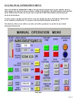
Page 20: ...u will function when the saw hood is open except the START blade function the head up and the head down buttons You have to have a profile selected in order to use the manual operation The indicator lights on the screen will tell you whether the vise is open or closed and what position the head is in The functions of this screen will be covered in each of the operations it is used for in more deta...

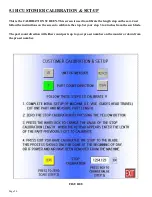
Page 21: ... length stop on the saw Just follow the instructions on the screen to calibrate the stop Set your stop 3 to 4 inches from the saw blade The part count direction will either count parts up to your pre set number on the counter or down from the pre set number FIGURE 5 THIS PAGE LEFT BLANK INTENTIONALLY FIGURE 8 ...

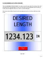
Page 22: ... will open Move the stop until the desired length appears on the screen The stop has a fine adjustment knob on it that you can fine tune the length with when you are close to your desired length The screen reads in 004 increments but the fine adjustment can be set in between 004 values on the screen FIGURE 9 ...

Page 23: ...anged The vise release setting chooses whether the vise opens when the blade is down or up Having the vise release in the down position will speed up the cutting operation This works well for most operations however if you are cutting short pieces that may get caught by the blade on the upstroke you need to choose vise release up FIGURE 10 ...

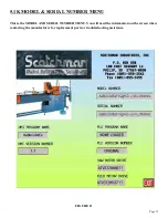
Page 24: ...5 1K MODEL SERIAL NUMBER MENU This is the MODEL AND SERIAL NUMBER MENU You will need the information on the screen when contacting the manufacturer for replacement parts or troubleshooting assistance FIGURE 11 ...

Page 25: ...ge 24 5 1L MAINTENANCE MENU This is the MAINTENANCE MENU The PLC menu is used for most troubleshooting problems The VFD menu is used for the same Each menu will be covered on the following pages FIGURE 12 ...

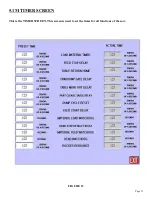
Page 26: ...Page 25 5 1M TIMER SCREEN This is the TIMER SCREEN This screen is used to set the times for all functions of the saw FIGURE 13 ...

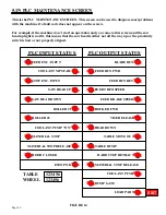
Page 27: ...RD STOP RETRACT DUMP GATE COOLANT PUMP LOAD PART PLC INPUT STATUS PLC OUTPUT STATUS TABLE 123456 WHEEL 123456 EXIT 5 1N PLC MAINTENANCE SCREEN This is the PLC MAINTENANCE SCREEN This screen can be used to diagnose most problems with the machine if a fault code does not appear on the screen For example if the machine won t start an operation and you come to this screen and the saw head up light is ...

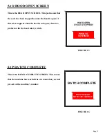
Page 28: ...NTINUE Page 27 This is the HEAD OPEN SCREEN This just means that the cycle has been stopped because the hood is open If this screen appears and the hood is not open there is a problem with the hood safety switch This is the BATCH COMPLETE SCREEN This means that the machine has reached the cut count that you had pre set on the machine s counter ...

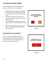
Page 29: ...rs or is bound up somehow on the supply table causing the machine to time out 3 You may have the brake distance set to where the brake cycle starts too soon causing the cycle to time out 4 If you are cutting a longer piece you may need to just increase the material feed watchdog in the timers set up menu FIGURE 17 5 1R LOAD FAULT SCREEN This is the LOAD FAULT SCREEN This tells you that the bundle ...

Page 30: ... This means that the cut cycle timed out before the head reached the down position You will need to increase the down feed rate or edit the material feed watchdog in the timer menu FIGURE 19 5 1T ALARMS HISTORY MENU This is the ALARMS HISTORY MENU FIGURE 20 ...

Page 31: ...value on the parts counter The value on the parts counter must be higher than the actual count number Make sure that the up and down stroke of the head is properly set for the material that you are cutting and that the vise is properly adjusted Start the coolant system and press the cycle start to start the operation The machine will run until the pre set quantity on the counter is reached or the ...

Page 32: ...CAUTION THIS MACHINE IS DESIGNED TO USE CARBIDE TIPPED BLADES ONLY USE ONLY BLADES DESIGNED FOR THIS MACHINE DO NOT MODIFY ANY BLADE TO FIT THIS MACHINE DO NOT USE BLADES DESIGNED FOR THIS MACHINE ON ANY OTHER EQUIPMENT THE MAXIMUM RPM S FOR THESE BLADES ARE 4 000 FIGURE 22 ...

Page 33: ...BACK LASH MUST BE TAKEN UP EVERY TIME THAT A BLADE IS CHANGED 8 After taking up the back lash tighten the blade bolt B 9 Break in the saw blade The teeth on new or re sharpened blades have a very sharp edge and should be fed through the first three or four cuts very slowly before starting normal cutting 10 Page 32 The CPO 315 RFA NF saw is designed to use a maximum 12 inch 300mm diameter blade The...

Page 34: ...A 90 ONLY Ø3 Ø76 Ø3 Ø76 Ø3 1 2 Ø89 2 1 2 X 2 1 2 63 X 63 3 1 8 X 3 1 8 79 X 79 N A N A FERROUS FERROUS NF NF 2 1 2 X 2 1 2 63 X 63 2 1 2 X 2 1 2 63 X 63 3 1 8 X 3 1 8 79 X 79 2 1 2 X 2 1 2 63 X 63 3 1 8 X 3 1 8 79 X 79 Ø3 Ø76 Ø3 Ø76 Ø3 1 2 Ø89 3 X 2 1 2 76 X 63 3 1 2 X 2 3 4 89 X 70 3 X 2 1 2 76 X 63 Ø1 3 4 Ø44 Ø1 3 4 Ø44 Ø1 3 4 Ø44 1 1 2 X 1 1 2 38 X 38 2 1 2 X 2 1 2 63 X 63 3 1 8 X 3 1 8 79 X 79...

Page 35: ...ubricant designed for automatic oilers 2 Slide the shuttle valve F on the filter lubricator device down to the closed position 3 Connect the air supply to the shuttle valve Make sure that the vise is clear and that the head is in the UP position 4 Slide the shuttle valve up to open the valve Whenever the shuttle valve is closed it bleeds the air pressure out of the system automatically FIGURE 24 P...

Page 36: ...g device disconnect the air supply and remove the plastic bowl The bowl is threaded and is removed by turning the threaded collar G Fill the bowl approximately 3 4 full of a quality ISO 22 air line lubricant designed for automatic oilers and screw it back TO ADJUST THE VISE TO THE SIZE OF MATERIAL BEING CUT 1 Open the vise using the positioning handle E and place the material in the vise 2 Crank t...

Page 37: ...Page 36 6 4 POWER DOWN FEED REFER TO FIGURE 26 BELOW FIGURE 26 ...

Page 38: ... saw starts to load up back the rate off by 1 4 of a turn Many things including the type of material being cut the blade RPM and the condition of the blade will affect the down feed rate 6 5 MATERIAL CLAMPING Page 37 CAUTION ALWAYS DISCONNECT THE AIR SUPPLY BEFORE REMOVING THE FILLER PLUG FROM THE RESERVOIR IF THE FILLER PLUG IS REMOVED WHILE THE MACHINE IS CONNECTED TO AIR PRESSURE THE FLUID IN T...

Page 39: ...t on the upper stroke C and adjust the upper stroke down to the head and lock it in position 6 Open the flow control and allow the head to travel on down to a point where the blade will have just cut completely through the material 7 Close the flow control and loosen the bolt on the lower stroke control B adjust the lower stroke up to the head and lock it in position 8 Open the flow control and pr...

Page 40: ...F G A B C FIGURE 27 NOTE HOOD AND BLADE GUARD ARE NOT SHOWN FOR CLARITY Page 39 ...

Page 41: ... buttons have to be pressed simultaneously for five seconds The keypad has the following functions F entry in to parameter selection and parameter end of programming RE SET select digit to be changed SET increment a digit between 0 and 9 REGISTERS N FUNCTION RANGE 03 Decimal point 0 3 07 Sign 0 active 1 inactive 08 Pulse factor 0 0001 9 9999 14 Display brightness 0 9 dark PROGRAMMING EXAMPLE Modif...

Page 42: ...material Failure to adjust this will allow the machine to load more than one part at a time Set the material diameter adjustments 3 Place the main disconnect switch in the on position and press the manual operation button in the main menu 4 Make sure that the hood is closed and the e stop is out 5 Make sure that you have the correct profile loaded for the part that you are going to cut 6 Press the...

Page 43: ...ump button 12 Press the head up button and the vise open button 13 Check the part that you have cut If it is the correct length press the auto button on the screen This will take you to the auto operation screen 14 Make sure that the correct profile is loaded on this screen that there is a value entered in the part count field and actual count is re set 15 Press the coolant start button and the cy...

Page 44: ...igh temperature bearing grease daily Clean the chips out of the vise at least once a day more often if needed Apply penetrating oil to the spindle and guide pins Clear the chips with a brush or similar device DO NOT use compressed air Check the oil level in the air lubricator device daily Use a quality ISO 22 air line lubricant FIGURE 30 Page 43 C B A ...

Page 45: ...cants and oils will greatly increase the life of this equipment We recommend our P N 075760 coolant SYNCON 2 straight and not diluted For the power down feed reservoir use a SAE 10W ISO 32 non foaming hydraulic oil such as Mobil DTE 10 or equivalent For the air lubricator use a quality ISO 22 air line lubricant designed for automatic oilers ...

Page 46: ...d not diluted Check the level of the hydraulic fluid in the power down feed reservoir Use a SAE 10W ISO 32 non foaming hydraulic oil such as Mobil DTE 10 or equivalent CAUTION ALWAYS DISCONNECT THE AIR SUPPLY BEFORE REMOVING THE FILLER PLUG FROM THE RESERVOIR IF THE FILLER PLUG IS REMOVED WHILE THE MACHINE IS CONNECTED TO AIR PRESSURE THE FLUID IN THE TANK WILL BE PURGED THROUGH THE OPENING UNDER ...

Page 47: ...Page 46 8 4 SPINDLE BEARING REPLACEMENT REFER TO FIGURE 31 BELOW FIGURE 31 ...

Page 48: ...om the saw The housing F fits snugly in the frame E and may have to be tapped out with a hammer 3 Gently tap two steel wedges opposite of each other between the housing F and the bearing retainer K 4 Place the assembly in a press resting on the steel wedges and press the spindle and bearing out of the housing F 5 Remove the snap ring H and press the bearing I off the spindle shaft L 6 Press the ne...

Page 49: ...Page 48 8 5 SPINDLE REPLACEMENT MAIN VISE SEE FIGURE 32 BELOW FIGURE 32 ...

Page 50: ...le and reassemble the vise reversing the above steps 8 6 SEAL REPLACEMENT MAIN VISE SEE FIGURE 32 ON PAGE 48 1 Make sure that the power and air supply to the machine are both off 2 Remove the bolts A B and the retainer D 3 Remove the clevis pin F and the cylinder clevis E and the forks CC 4 Remove the two lower bolts C and remove the cylinder H from the machine 5 Place the cylinder in a vise and r...

Page 51: ...ns are provided with complete installation instructions 9 3 DIGITAL READOUT A digital readout for the stop assembly on this machine is available It is used as the length stop for the machine For parts identification REFER TO SECTION 12 2 9 4 OVERTURN DEVICE This option is used in conjunction with the square tube jaws This device is used to position square tubing as it comes off of the supply table...

Page 52: ...nd the motor still will not run contact your dealer or the factory 2 THE SAW MOTOR RUNS BUT DOES NOT HAVE ADEQUATE POWER A Make sure that the supply voltage and phase correspond to the saw motor s voltage and phase B Disconnect the machine from the power source and check for any loose or disconnected wires C The supply lines to the machine must be of adequate size to handle the load FOR RECOMMENDE...

Page 53: ...installing a blade For instructions REFER TO SECTION 6 2 Also check the condition of the drive pins when replacing the blade If the drive pins are broken or worn replace them 6 Keep the blade flange the face of the blade spindle and the blade clean and free from nicks Any contamination or nicks on the flange spindle or the blade will cause the blade to run out of alignment 5 Have your blades re sh...

Page 54: ... of the reservoir B Check the level of the coolant in the reservoir We recommend our P N 075760 coolant SYNCON 2 straight and not diluted C Check the reservoir for contamination or sludge buildup that may be blocking the inlet D Remove the coolant line from the guard and make sure that it s clear Also make sure that the valve on the guard is open Page 53 SEE SECTION 11 11 11 15 for coolant system ...

Page 55: ...RE 34 ON THE FOLLOWING PAGE Worn seals in the vise supply table or discharge assembly cylinders For seal kit installation instructions REFER TO SECTION 8 5 CAUTION THE AIR SUPPLY TO THE MACHINE MUST BE DISCONNECTED BEFORE YOU REMOVE THE FILLER PLUG FROM THE RESERVOIR FAILURE TO DISCONNECT THE AIR WILL CAUSE THE FLUID TO BE PURGED OUT THROUGH THE OPENING UNDER PRESSURE Low levels of fluid in the re...

Page 56: ...NDER 4B 1 4 RED TO FRONT OF MATERIAL STOP CYLINDER 5A 1 4 RED TO BACK OF EJECT DUMP CYLINDER 5B 1 4 BLUE TO FRONT OF EJECT DUMP CYLINDER 6A 1 4 YELLOW TO FRONT OF DUMP ACTUATOR 6B 1 4 BLACK TO BACK OF DUMP ACTUATOR 7A 1 4 GREEN TO LEFT SIDE OF TEE TO INFEED ACTUATOR 7B 1 4 GREEN TO RIGHT SIDE OF TEE TO INFEED ACTUATOR 8A 1 4 GREEN TO BACK OF STOP CLAMP 8B 1 4 BLUE TO FRONT OF STOP CLAMP 9A 1 4 YEL...

Page 57: ...Page 56 WWW SCOTCHMAN COM BEST IN THE BUSINESS WARRANTY S C O T C H M A N ...

Page 58: ...Page 57 SCOTCHMAN CPO 315 RFA NF SAW SCOTCHMAN INDS 180 E US HWY 14 PO BOX 850 PHILIP SD 57567 Call 1 605 859 2542 WWW SCOTCHMAN COM ...

Page 59: ... 077900 Bearing Housing G 077909 Needle Bearing H 077897 Snap Ring 33mm I 075077 Bearing J 075075 Seal K 077896 Seal Flange L 077894 Spindle Shaft M 077626 Saw Flange N 077908 M 10 Bolt Left Hand N1 080193 Wrench Blade Flange P 077902 Key 8 x 25 Q 677901 M 10 SHCS R 046094 Wire Clip S 221120 M 8 x 25 SHCS T 077864 M 5 x 12 SHCS U 077912 Pivot Shaft Housing V 077329 Pivot Pin Short W 077341 Pivot P...

Page 60: ...Page 59 EE 073328 M 8 x 40 HHCS FF 073326 M 8 x 25 HHCS GG 073920 M 10 Dowel Pin 077929 Spindle Assembly Includes F G H I J K L FIGURE 35 ...

Page 61: ... Down Plate N 221210 M 10 x 25 SHCS O 045304 Vise Side Plate P 221412 M 16 x 35 SHCS Q 045307 Upper Wear Plate R 230005 M 6 x 12 FSHCS S 077100 M 10 Dowel Pin T 045303 End Plate U 201620 M 16 x 65 HHCS V 045308 Lower Wear Plate W 073458 M 6 x 10 SHCS X 045325 Lead Screw Cover Y 045602 Spring Z 201160 M 8 x 60 HHCS AA 045314 Detent Block BB 045309 Lead Screw CC 045198 Drive Forks DD 045310 Boss EE ...

Page 62: ...e 61 JJ 219047 M 10 x 10 Set Screw KK 077798 Vise Jaws LL 203212 M 10 x 30 HHCS MM 045224 Strike Plate NN 060270 Covering Cap OO 114020 Washer PP 210012 M 10 Jam Nut 045300 Complete Vise Assembly FIGURE 36 ...

Page 63: ... 20 Hex Nut I 043082 Idler Sprocket J 221317 M 12 SHCS K 218022 M 6 Set Screw L 042045 Drive Sprocket Assembly M 046048 M 35 Snap Ring N 101412 1 2 13 x 1 HHCS O 208014 M 12 Hex Nut P 046120 35 Chain 47 Links Q 046110 35 Chain 43 Links Q1 046033 35 Chain Conn Link not shown R 218022 M 6 Set Screw S 043050 Bearing Spacer T 045618 Keeper U 112014 1 2 Lock Washer V 044124 Key X 221115 M 8 x 20 SHCS Y...

Page 64: ...Page 63 AA 077191 Snap Ring BB 046006 Drive Sprocket Bearing FIGURE 37 A B C D E D Z F G H O I K V L Y A B A B R S Q P X T J M N U ...

Page 65: ... Roller J 045243 Guide Plate K 045235 Rear Side Plate L 045237 Sensor Mount M 077788 Proximity Switch N 221120 M 8 SHCS O 221210 M 10 x 25 SHCS P 201417 M 12 SHCS Q 208014 M 12 Hex Nut R 229220 M 10 Shoulder Bolt S 047643 Coupler T 047644 5 8 Flange U 047650 3 4 Flange V 046563 Drive Wheel V1 044410 Abrasive Wheel Cover W 045580 Drive Motor X 045566 Pulley Y 045570 Belt Z 045565 Pulley AA 045595 E...

Page 66: ...Page 65 FIGURE 38 ...

Page 67: ...1 2 x 13 x 1 1 2 HHCS F 221230 M 10 x 60 SHCS G 045139 Sprocket Mount H 046115 35 Chain 46 Link H1 046033 Connecting Link I 042051 Drive Sprocket J 043078 Space Block K 046240 Infeed Guard L 121205 3 8 x 1 SHCS M 045295 Roller Cover N 077746 Fittings O 044124 Key P 221222 M 10 x 45 SHCS Q 112014 1 2 Lock Washer R 212012 M 10 Lock Washer S 208012 M 10 Nut ...

Page 68: ...Page 67 FIGURE 39 ...

Page 69: ...ssembly B 079213 Vertical Guide Roller C 229220 M 12 x 20 x 50 Shoulder Bolt D 045279 Roller Mount E 043003 Nylon Roller F 229225 M 10 x 12 x 70 G 221210 M 10 x 25 SHCS H 114020 Hardened Washer I 043018 Roller Mount J 045426 Vertical Mount K 080061 Handle L 221212 M 10 x 30 SHCS ...

Page 70: ...Page 69 FIGURE 40 ...

Page 71: ... Spacer F 046563 Rubber Wheel F1 044410 Abrasive Band G 046046 Snap Ring H 045564 Bearing I 045291 Hub Bolt J 045290 Wheel Insert K 045566 Wheel Pulley L 045570 Belt M 073605 6 x 32 x 5 8 SHCS N 045321 Brass Bushing O 229415 M 10 x 12 x 16 Shoulder Bolt P 045595 Encoder 500 Pulse Q 045565 Encoder Pulley 045567 Encoder Cord ...

Page 72: ...Page 71 FIGURE 41 ...

Page 73: ...ht End Plate L 045542 Coupler M 045160 Adjustable Cylinder Mount N 046585 Cylinder N1 045654 Cylinder Seal Kit O 045154 Slide W Cylinder Mount P 229225 Shoulder Bolt Q 043003 Guide Roller R 230207 M 10 x 20 FSHCS S 045165 Table T 045158 Table Slide U 026746 Retainer V 073458 M 6 x 10 SHCS W 046702 Bearing X 016402 Snap Ring Y 045164 Table Slide Rail Z 114020 Washer AA 221212 M 10 x 30 SHCS BB 0777...

Page 74: ...Page 73 Y 045164 Table Slide Rail Z 114020 Washer AA 221212 M 10 x 30 SHCS BB 077746 1 4 x 90 Swivel Fitting CC 045581 Cylinder Clevis DD 045582 Clevis Pin FIGURE 42 ...

Page 75: ...0014 M 6 x 10 BHCS M 104240 3 8 x 24 x 4 HHCS N 044130 Trigger Stud O 045454 End Plate P 221120 M 8 x 25 SHCS Q 044140 Shaft Support R 221212 M 10 x 30 SHCS S 044167 Collett Mount T 045602 046652 218048 Spring Ball M 10 Set Screw U 044136 Scale Pointer V 044135 Detent Holder W 221310 M 12 x 25 SHCS X 044172 Base Plate Y 044232 Linear Bearing Z 073450 M 4 x 16 SHCS AA 073626 M 10 x 20 SHCS BB 20802...

Page 76: ...Page 75 FIGURE 43 ...

Page 77: ...15 3 16 x 1 1 2 Roll Pin I 047601 Stop Cylinder J 045286 Stop Guide K 077795 60 Proximity Switch K1 047172 90 Proximity Switch K2 047172 120 Proximity Switch L 218022 M 6 x 6 Set Screw M 045288 Stop Block N 130520 1 2 20 x 1 1 2 FSHCS O 045607 Spring P 141220 7 32 x 1 3 4 Roll Pin Q 077156 M 6 x 8 x 12 Shoulder Bolt R 045289 Bumper S 077743 1 8 NPT x 1 4 Plastic Ninety Degree T 073455 M 5 x 20 SHC...

Page 78: ...Page 77 FIGURE 44 ...

Page 79: ...215 ISO 4762 M 10 x 35 18 229211 M 8 x 10 x 20 Shoulder Bolt 3 214012 M 10 Flat Washer 24 208012 M 10 x 1 5 Din934 Hex Nut 41 221210 M 10 x 25 SHCS 6 221220 M 10 x 40 SHCS 17 221212 M 10 x 30 SHCS 42 073619 M 6 x 20 SHCS 3 045407 Cylinder 3 045402 Cylinder Clevis 5 229225 M 10 x 12 x 70 SB912 2 049300 1 0 Coupler 6 6 5 5 31 27 2 045134 Guide Rod 28 1 045540 3 4 Coupler 29 17 114020 3 8 Flat Washer...

Page 80: ...Page 79 6 30 31 20 26 7 5 DETAIL B 24 25 17 16 18 10 DETAIL A 4 21 30 22 23 15 14 16 12 11 20 19 18 9 DETAIL C 38 37 8 31 30 3 2 20 32 33 35 33 36 34 20 9 13 13 28 27 29 B A C FIGURE 45 ...

Page 81: ... Bearing 3 1 079211 Roller Shaft 4 2 214016 M 16 Washer 5 1 079212 Roller Stand 6 1 079213 Vertical Roller 7 1 229220 M 10 x 12 x 50 SH Bolt 8 1 219047 M 10 x 12 SS 9 1 045105 Stand Ass y 10 1 114020 3 8 Flat Washer 11 1 201232 M 10 x 80 HHCS 12 2 208024 M 24 Hex Nut 13 1 049217 Foot Ass y 14 1 049330 Foot Clamp ...

Page 82: ...Page 81 FIGURE 46 ...

Page 83: ...7715 Pivot Bolt Package of 2 D 045232 Cylinder Bracket E 077512 TPC Cyl Nut Machined F 041015 Right Angle Flow Control G 221212 M 10 x 30 SHCS H 047100 Upper Bracket Assembly I 221210 M 10 x 25 SHCS J 045054 1 2 90 Degree Swivel K 077720 Reducer L 077716 Cylinder Clevis Includes N P 078455 Sight Glass Q 077700 Bellow ...

Page 84: ...Page 83 FIGURE 47 ...

Page 85: ...77701 Baffle C 077777 3 8 NPT Plug D 045054 1 2 x Ninety Degree Swivel x 169PL E 077536 Check Valve F 045042 1 2 Straight Fitting J 047535 Flow Control Valve K 045054 1 2 x Ninety Degree Swivel x 169PL L 077779 1 4 NPT Close Nipple M 077771 Reducer N 045041 Brass Tee O 078455 Sight Glass ...

Page 86: ...Page 85 FIGURE 48 ...

Page 87: ...045593 1 6 Snap Ring 016402 2 7 PD Clevis Drill 045594 1 8 Bellow Clamp For 045697 045693 1 9 Bellow Retainer 045696 1 10 Bellow For 045699 045697 1 11 Cylinder Pivot Bolt 2 077715 1 12 M6 X 6MM DIN916 Set Screw 218022 2 13 M6 X 10MM DIN BN19 BHCS 220014 2 14 Cylinder Seal Kit For 045699 045698 1 15 Return Spring 077211 2 16 M10 X 25MM DIN912 SHCS 221210 8 17 Includes Items 6 7 Includes Items 3 14...

Page 88: ...Page 87 FIGURE 49 ...

Page 89: ...ION A 045560 Cable End B 677728 Fitting 1 4 NPT to 1 4 ITOS C 077777 Plug 3 8 NPT D 045045 Vent 3 8 E 077738 90 Degree Elbow E1 077771 Bushing F 045650 Solenoid G 045655 Valve H 077744 Fitting I 077930 Coolant Regulator J 045603 Complete Valve Assembly ...

Page 90: ...Page 89 FIGURE 50 ...

Page 91: ...LADE GUARD ASSEMBLY ITEM PART DESCRIPTION A 045267 Guard Shell B 677901 M 10 SHCS I 076839 Mister Unit J 676842 Fitting K 077926 Coolant Line L 060501 Air Line M 676844 Hose Barb N 073095 M 4 Washer O 073415 M 4 SHCS ...

Page 92: ...Page 91 FIGURE 51 ...

Page 93: ...sting 25mm Bore DA 077381 End Casting 30mm Bore E 075049 Motor Bearing 6205Z 25mm EA 077325 Motor Bearing 6206 30mm F 077191 Snap Ring G 076369 Key H 203210 M 10 SHCS I 077370 Key 6 x 4 x 32mm J 077376 Seal K 075050 Spacer Washer L 076556 Snap Ring 30mm Only M 077378 End Casting Front COMPLETE MOTORS A 076986 230 Volt B 076985 460 Volt C 076988 575 Volt ...

Page 94: ...Page 93 FIGURE 52 ...

Page 95: ...0V 5HP 230V VFD Programmed Comm Module 30A Disconnect Black Terminal Crossover Cable Not Shown PLC RFA Touch Screen PLC Battery RFA Touch Screen PLC Memory RFA Touch Screen Power Supply Slim Interface Relay 24VDC Secondary Fuse 2 AMP ITEM A B C D E F G H I J K L M N O 460v 1 2 HP VFD Programmed A1 045530 045529 078286 8A Breaker 460V 15A Breaker 460V 5HP 460V VFD Programmed B1 C1 D1 Disconnect Sha...

Page 96: ...al White Terminal Ground Terminal Terminal Barrier Terminal Anchor 2P Fuse Holder 1P Mini Fuse Holder Terminal Jumper 1A Fuse 3A Fuse Patch Cable Relay Jumper Disconnect Handle HMI Screen Not Shown Q R S T U V W X Y Z AA BB CC DD EE FF GG HH II PART DESCRIPTION ITEM NOTE S N B2053RFA0522 and up All RFA saws have this update after this S N However two earlier 480Vsaws S N B2047RFA1220 B2050RFA0621 ...

Page 97: ...FIGURE 53 FIGURE 55 CC X EE EE BB G V W Y Z E P M FF A D BB GG AA O N B C Q S F J HH R T U DD I K L Page 96 ...

Page 98: ...Page 97 THIS PAGE LEFT BLANK INTENTIONALLY ...

Page 99: ...Nut D 045171 Base Cabinet E 045735 Lower Enclosure G N A H 046642 Door Assembly I 049217 Leveling Pads I1 208024 M 24 Nut J 049330 Foot Clamp K 073617 M 6 x 12 BHCS L 046018 Handle M 045052 Chip Bucket N 045257 Reservoir Screen O 046640 Access Cover P 220010 M 4 x 12 BHCS Q 073350 M 10 x 100 HHCS R 114020 Hard Washer ...

Page 100: ...Page 99 FIGURE 54 ...

Page 101: ...N A 677728 1 4 NPT x 1 4 Hose B 677745 1 4 Brass Tee C 077748 1 4 To 1 8 NPT Reducer D 077750 1 8 x 2 1 2 Pipe Nipple E 077930 Mister Regulator F 677933 Mister Reservoir G 077779 1 4 Brass Nipple H 077741 5 16 Elbow I 045740 Check Valve J 077926 Mister Line ...

Page 102: ...Page 101 FIGURE 55 ...

Page 103: ... 045299 Stop Block D 045320 Stroke Sensor Mount E 045330 Stop Guide F 220010 M 4 x 12 BHCS G 203212 M 10 x 30 HHCS H 114020 M 10 Flat Washer I 077796 Proximity Switch J 221212 M 10 x 30 SHCS K 221210 M 10 x 25 SHCS L 221120 M 8 x 25 SHCS M 158202 Bumper N 047104 Stroke Control Plate O 221212 M 10 x 30 SHCS P 073095 M 4 Washer ...

Page 104: ...Page 103 FIGURE 56 ...

Page 105: ...eal J 229415 M 10 x 12 x 16 Shoulder Bolt K 047151 Hood Painted L 077142 Grease Nipple M 077100 M 10 Dowel Pin N 073617 M 6 x 12 BHCS O 040012 Bumpers P 047110 Hood Safety Switch P1 047115 Switch Mount P2 220010 M 4 BHSC P3 215000 M 4 Nylon Lock Nut Q 215013 M 8 Nylon Lock Nut R 077329 Short Pivot Pin S 077341 Long Pivot Pin T 047155 Complete Hood Assembly Includes D F G K N O ...

Page 106: ...Page 105 FIGURE 57 ...

Page 107: ...UIPMENT PARTS LISTS UNIT PART 1 Gal 1 Qt 1 Gal 075760 075753 075759 DESCRIPTION 1 GAL SYNCON 2 Air Line Lubricant Air Line Lubricant do not dilute 55 Gal 075761 55 GAL SYNCON 2 do not dilute 12 1 CUTTING COOLANTS AND LUBRICANTS ...

Page 108: ... 073400 M 5 x 30 SHCS E 044092 Scale Assembly F 220100 M 3 x 10 SHCS G 208010 M 8 Hex Nut H 026504 M 8 x 16 Brass S S I 044090 Horizontal Mount J 073605 6 x 32 x 3 4 SHCS K 046652 Detent L 045602 M 8 Ball Spring M 218048 M 10 x 10 S S N 210012 M 10 Jam Nut O 047095 PEM Sensor P 073095 M 4 Washer Q 046668 Wire Clamp FIGURE 58 ...

Page 109: ...TURN DEVICE ITEM PART DESCRIPTION A 045344 Slider B 229212 M 8 x 10 x 60 Shoulder Bolt C 045346 Roller D 045348 Roller Bracket E 045347 Roller Bracket F 073420 M 8 x 16 SHCS G 221120 M 8 x 25 SHCS 045352 Overturn Device ...

Page 110: ...Page 109 FIGURE 59 ...

Page 111: ... C 077864 M 5 x 12 SHCS D 077742 1 4 Male Swivel x 169PL E 077744 1 4 x 5 16 NPT Fitting F 060501 5 16 Black Hose 047250 Complete Regulator Assembly 12 4A POWER DOWN FEED REGULATOR A 078190 Regulator B 677934 Mount C 077864 M 5 x 12 SHCS D 077746 1 4 x 90 Swivel E 077746 1 4 x 90 Swivel F 073758 Air Line G ...

Page 112: ...Page 111 FIGURE 60 ...

Page 113: ... Dump Table J 047220 047220 Slide Rail Support K 047208 047208 Support Block L 044214 044216 T Rail M 221210 221210 M 10 x 25 SHCS N 047430 044200 Center Leg O 221210 221210 M 10 x 25 SHCS P 047326 047226 Rail Support Assembly Q 044224 044226 Alum Beam R 044330 044330 Long Dump Table S 044152 044152 Dump Table Shaft T 044153 044153 Short Dump Table Shaft U 044158 044158 Support V Short Dump Table ...

Page 114: ...Page 113 FIGURE 61 ...

Page 115: ...0 24 23 34 0V 25 YELLOW RED 12 11 10 1 2 3 24V 15 14 13 16 4 5 6 7 8 9 12 GROUND 63 62 5HP 240 VOLT 1 2 HP 240 VOLT 1 8 HP 240 VOLT PA PB FOUND IN NF VERSION BRAKING RESISTOR PART PK9GTA GROUND LUG TA2 0 10AWG 10AWG 10AWG 12AWG 10AWG BLK 10AWG RED 10AWG BLU 10AWG 10AWG 10AWG 10AWG 12AWG BLK 12AWG RED 12AWG BLU 12AWG 12AWG 12AWG 12AWG 14AWG 14AWG BLK 14AWG RED 14AWG BLU 14AWG 14AWG 14AWG 14AWG 14AW...

Page 116: ...PS24030 50W TELEMECANIQUE 1T1 1T2 1T3 GND GND 2T3 2T2 2T1 GND 3T3 3T2 3T1 24 0V ATV320U40N4 ATV320UO4N4 YELLOW BLACK 28 27 26 19 18 17 31 30 29 33 32 22 21 20 24 23 34 0V 25 YELLOW RED 12 11 10 1 2 3 24V 15 14 13 16 4 5 6 7 8 9 2 12AWG GROUND 63 62 5HP 480 VOLT 1 2 HP 480 VOLT 1 8 HP 480 VOLT PA PB FOUND IN NF VERSION BRAKING RESISTOR PART PK9GTA GROUND LUG TA2 0 10 GRN 12 BRN 12 ORN 12 YEL 12 BRN...

Page 117: ...03 MODBUS T TAP CAT 5 MALE TO MALE CON ECAT5 4PR25BKB ECAT5 4PR25BKB 192 168 1 13 RS485 ETHERNET RJ45C5X01PU ETHERNET PORT ON TWIDO YELLOW BLACK 35 TELEMECANIQUE HMI A2 A1 ORANGE 1CR STOP 0V FROM PAGE 1 BROWN BARE WHITE YELLOW GREEN SEE PG 3 SEE PG 3 SEE PG 3 SEE PG 3 43 ROLLER SENSOR 1 YELLOW RED 15 12 8 YELLOW RED RED 1CR STOP RELAY 9 5 1CR STOP RELAY RED WHITE IN 13 37 33 YELLOW BLACK IN 12 44 ...

Page 118: ...L GRY RED GRAY ORN FROM PAGE 2 FROM PAGE 2 43 44 45 46 SHOWN AGAIN FROM CR1 ON PG 2 1A 3FU GCC1 24VDC COM R11 A2 A1 R12 A2 A1 R13 A2 A1 R14 A2 A1 R15 A2 A1 SD CARD TMASD1 SAW RUN CMD LOAD PART ROCKER HEAD DOWN VISE REL EJECT DUMP HARD STOP PART LENG STOP FEED FWD CMD FEED REV CMD FEED LOW SPD 1 FEED LOW SPD 2 COOLANT PUMP DUMP GATE A PUL WHL ENC B PUL WHL ENC CANNOT USE A PUL FINAL ENC B PUL FINAL...

Page 119: ...K FROM PAGE 3 0V NF OPTION BRAKE OVER TEMP IN 20 56 ORANGE WORK CELL STOP PROX SWITCH 57 ORN BLACK WORK CELL START PROX SWITCH 58 ORN BLUE REMOTE PB STATION START SWITCH 59 ORN WHITE IN 15 REMOTE PB STATION STOP SWITCH 60 YELL BLUE OPTIONAL DEVICES OPTIONAL DEVICES OPTIONAL DEVICES OPTIONAL DEVICES OPTIONAL DEVICES SEE PG 3 SEE PG 3 SEE PG 3 SEE PG 3 SEE PG 3 SEE PG 3 SEE PG 3 SEE PG 3 SEE PG 3 SE...

Page 120: ...PART 11 14 49 BLUE RED R3 11 14 48 BLUE YELLOW R2 11 14 47 GRAY YELLOW R1 4FU GCC 3A YELLOW RED 24V FROM PAGE 4 PART LENGTH STOP RELEASE 25 YELLOW BLACK 26 23 YELLOW BLACK BROWN WHITE 11 14 R8 54 30 FROM PAGE 4 0V RED YELLOW 11 14 R7 53 HARD STOP YELLOW BLACK 29 BLACK BLACK RED WHITE Scotchman Industries Cold Saw RFA SOFT START PANEL TERMINAL FIELD CONNECTION WIRES PLC PANEL TERMINAL R1C SOFT STAR...

Page 121: ...WHT BLK WHT PUR BLK R16 14 11 64 GRY WHT 65 BLK R16 12 11 66 PNK 67 ORN BLU 69 ORN BLK 68 ORN WHT R1C SAW VFD R1A SAW VFD R1B SAW VFD NOTE THIS RELAY IS ENERGIZED WHEN SAW VFD HAS RUN COMMAND PRESENT ON THE DRIVE NOTE THIS RELAY IS ENERGIZED WHEN SAW HAS A FAULT OCCUR OR REACHES END OF BATCH Scotchman Industries Cold Saw RFA SPECIAL OPTION SOFT START PANEL TERMINAL FIELD CONNECTION WIRES PLC PANEL...

Reviews: