Page 20
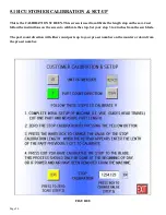
5.1H CUSTOMER CALIBRATION & SET-UP
This is the CALIBRATION SCREEN. This screen is used to calibrate the length stop on the saw. Just
follow the instructions on the screen to calibrate the stop. Set your stop 3 to 4 inches from the saw blade.
The part count direction will either count parts up to your pre-set number on the counter or down from
the pre-set number.
FIGURE 5
THIS PAGE LEFT BLANK INTENTIONALLY.
FIGURE 8
Summary of Contents for CPO-315-RFA-NF
Page 10: ...Page 9 FIGURE 1 A D E B C G I L F K ...
Page 12: ...Page 11 FIGURE 2 ...
Page 37: ...Page 36 6 4 POWER DOWN FEED REFER TO FIGURE 26 BELOW FIGURE 26 ...
Page 40: ...F G A B C FIGURE 27 NOTE HOOD AND BLADE GUARD ARE NOT SHOWN FOR CLARITY Page 39 ...
Page 47: ...Page 46 8 4 SPINDLE BEARING REPLACEMENT REFER TO FIGURE 31 BELOW FIGURE 31 ...
Page 49: ...Page 48 8 5 SPINDLE REPLACEMENT MAIN VISE SEE FIGURE 32 BELOW FIGURE 32 ...
Page 57: ...Page 56 WWW SCOTCHMAN COM BEST IN THE BUSINESS WARRANTY S C O T C H M A N ...
Page 66: ...Page 65 FIGURE 38 ...
Page 68: ...Page 67 FIGURE 39 ...
Page 70: ...Page 69 FIGURE 40 ...
Page 72: ...Page 71 FIGURE 41 ...
Page 76: ...Page 75 FIGURE 43 ...
Page 78: ...Page 77 FIGURE 44 ...
Page 82: ...Page 81 FIGURE 46 ...
Page 84: ...Page 83 FIGURE 47 ...
Page 86: ...Page 85 FIGURE 48 ...
Page 88: ...Page 87 FIGURE 49 ...
Page 90: ...Page 89 FIGURE 50 ...
Page 92: ...Page 91 FIGURE 51 ...
Page 94: ...Page 93 FIGURE 52 ...
Page 98: ...Page 97 THIS PAGE LEFT BLANK INTENTIONALLY ...
Page 100: ...Page 99 FIGURE 54 ...
Page 102: ...Page 101 FIGURE 55 ...
Page 104: ...Page 103 FIGURE 56 ...
Page 106: ...Page 105 FIGURE 57 ...
Page 110: ...Page 109 FIGURE 59 ...
Page 112: ...Page 111 FIGURE 60 ...
Page 114: ...Page 113 FIGURE 61 ...

