4.4 ELECTRICAL REQUIREMENTS
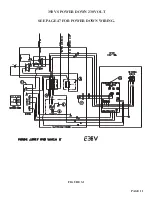
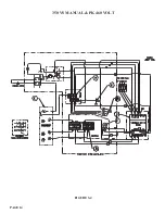
SEE FIGURE 3-1 THROUGH 3-4 ON THE FOLLOWING PAGES.
Ö
CAUTION: TO PREVENT DAMAGE TO THE MACHINE AND DANGER TO THE OPERATOR,
ALL ELECTRICAL CONNECTIONS SHOULD BE MADE BY A QUALIFIED ELECTRICIAN.
THIS MACHINE OPERATES WITH LIQUID COOLANT AND MUST BE GROUNDED IN
ACCORDANCE WITH NATIONAL ELECTRIC CODES.
All machines are wired for three phase power. The motors and coolant pumps are dual voltage and will
operate on either 230 or 460 volts; the Variable Speed Drive is not. If the machine is not the same voltage
as your plant voltage, you will have to replace the variable speed drive, change the primary leads on
the transformer and rewire the motor. To insure satisfactory performance, the supply voltage should be
(+ or -) 10% of the motor voltage rating. Check the motor data tag for full load current requirements.
Single phase motors are not available; however, the Variable Speed Drive can be used as a phase
converter. For supply lines ten feet (303 cm) or shorter, we recommend 12 gauge wire. For lines longer
than ten feet (303 cm), we recommend 10 gauge wire. We do not recommend supply lines over twenty feet
(606 cm) in length.
CPO-350 (11-176 RPM)
MOTOR VOLTAGE
FULL LOAD CURRENT
HORSEPOWER
208
22
5
230
20
5
460
10
5
PAGE 10
Summary of Contents for CPO 350
Page 1: ...CPO 350 VARIABLE SPEED COLD SAW PRINTED SEPTEMBER 2014...
Page 7: ...PAGE 7 FIGURE 1...
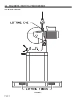
Page 8: ...4 2 MACHINE MOVING PROCEDURES SEE FIGURE 2 BELOW PAGE 8 FIGURE 2...
Page 11: ...PAGE 11 350 VS POWER DOWN 230 VOLT SEE PAGE 47 FOR POWER DOWN WIRING FIGURE 3 1...
Page 12: ...PAGE 12 350 VS MANUAL PK 230 VOLT FIGURE 3 2...
Page 13: ...PAGE 13 350 VS POWER DOWN 460 VOLT SEE PAGE 47 FOR POWER DOWN WIRING FIGURE 3 3...
Page 14: ...PAGE 14 350 VS MANUAL PK 460 VOLT FIGURE 3 4...
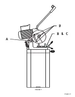
Page 17: ...PAGE 17 FIGURE 4...
Page 19: ...PAGE 19 FIGURE 5...
Page 27: ...PAGE 27 FIGURE 8 FIGURE 9...
Page 29: ...PAGE 29 FIGURE 10...
Page 33: ...PAGE 33 FIGURE 12...
Page 35: ...PAGE 35 FIGURE 13...
Page 37: ...PAGE 37 FIGURE 14...
Page 39: ...PAGE 39 FIGURE 15...
Page 41: ...PAGE 41 FIGURE 16...
Page 43: ...PAGE 43 FIGURE 17...
Page 45: ...7 2F POWER DOWN FEED WIRING DIAGRAM Ser s 6425 Up PAGE 45 FIGURE 19...
Page 46: ...7 2G PNEUMATIC SCHEMATIC POWER DOWN MACHINES PAGE 46 FIGURE 20...
Page 47: ...THIS PAGE LEFT BLANK INTENTIONALLY PAGE 47...
Page 49: ...PAGE 49 FIGURE 21...
Page 51: ...PAGE 51 FIGURE 22...
Page 55: ...PAGE 55 FIGURE 23...
Page 59: ...PAGE 59 FIGURE 25...
Page 61: ...PAGE 61 FIGURE 26...
Page 63: ...PAGE 63 FIGURE 27...
Page 65: ...PAGE 65 FIGURE 28...
Page 67: ...PAGE 67 FIGURE 29...
Page 69: ...PAGE 69 FIGURE 30...
Page 71: ...PAGE 71 FIGURE 31...
Page 73: ...PAGE 73 FIGURE 32...
Page 75: ...PAGE 75 FIGURE 33...
Page 77: ...PAGE 77 FIGURE 33...
Page 79: ...PAGE 79 FIGURE 34...
Page 81: ...PAGE 81 FIGURE 35...
Page 83: ...PAGE 83 FIGURE 36...
Page 85: ...PAGE 85 FIGURE 37...
Page 87: ...PAGE 87 FIGURE 38...
Page 89: ...PAGE 89 FIGURE 39...
Page 91: ...PAGE 91 FIGURE 40...
Page 93: ...PAGE 93 FIGURE 41...


