6.3 SELECTING THE PROPER BLADE AND CUTTING SPEED
In cold sawing, there is no such thing as a general purpose blade. To achieve the best results from your
saw, proper blade selection is important. Each saw is shipped with a pitch (number of teeth) calculator,
which will help to determine the proper blade for your application.
When sawing flat stock or rectangular solid sections, determine the thickest section that will be cut and
use the equivalent square size on the pitch calculator to determine the proper blade.
The CPO-350 Variable Speed saw is designed to use a maximum 14 inch (350mm) diameter blade. We
recommend using smaller diameter blades if your application does not require the maximum diameter.
Using smaller diameter blades reduces the surface feet per minute and smaller blades provide greater
rigidity. Smaller diameter blades available from stock for this machine are a 12-1/2 inch (315mm) and a
10-3/4 inch (275mm). For available tooth styles in stock, REFER TO SECTION 11.0.
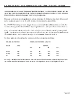
The chart below gives the surface feet per minute for the various diameter blades.
BLADE DIAMETER
SURFACE FEET PER MINUTE
INCH
MM
RPM’S
11
35
88
176
10-3/4
275
31
99
247
500
12-1/2
315
36
114
287
572
14
350
41
128
322
646
The proper blade speed is also important. The CPO-350 Variable Speed has an RPM range from 11 to
176. The heavier the material, the lower the RPM. The lighter the material, the higher the RPM.
PAGE 25
Summary of Contents for CPO 350
Page 1: ...CPO 350 VARIABLE SPEED COLD SAW PRINTED SEPTEMBER 2014...
Page 7: ...PAGE 7 FIGURE 1...
Page 8: ...4 2 MACHINE MOVING PROCEDURES SEE FIGURE 2 BELOW PAGE 8 FIGURE 2...
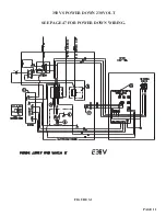
Page 11: ...PAGE 11 350 VS POWER DOWN 230 VOLT SEE PAGE 47 FOR POWER DOWN WIRING FIGURE 3 1...
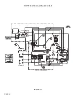
Page 12: ...PAGE 12 350 VS MANUAL PK 230 VOLT FIGURE 3 2...
Page 13: ...PAGE 13 350 VS POWER DOWN 460 VOLT SEE PAGE 47 FOR POWER DOWN WIRING FIGURE 3 3...
Page 14: ...PAGE 14 350 VS MANUAL PK 460 VOLT FIGURE 3 4...
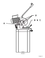
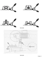
Page 17: ...PAGE 17 FIGURE 4...
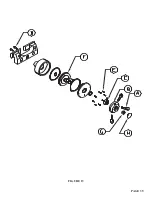
Page 19: ...PAGE 19 FIGURE 5...
Page 27: ...PAGE 27 FIGURE 8 FIGURE 9...
Page 29: ...PAGE 29 FIGURE 10...
Page 33: ...PAGE 33 FIGURE 12...
Page 35: ...PAGE 35 FIGURE 13...
Page 37: ...PAGE 37 FIGURE 14...
Page 39: ...PAGE 39 FIGURE 15...
Page 41: ...PAGE 41 FIGURE 16...
Page 43: ...PAGE 43 FIGURE 17...
Page 45: ...7 2F POWER DOWN FEED WIRING DIAGRAM Ser s 6425 Up PAGE 45 FIGURE 19...
Page 46: ...7 2G PNEUMATIC SCHEMATIC POWER DOWN MACHINES PAGE 46 FIGURE 20...
Page 47: ...THIS PAGE LEFT BLANK INTENTIONALLY PAGE 47...
Page 49: ...PAGE 49 FIGURE 21...
Page 51: ...PAGE 51 FIGURE 22...
Page 55: ...PAGE 55 FIGURE 23...
Page 59: ...PAGE 59 FIGURE 25...
Page 61: ...PAGE 61 FIGURE 26...
Page 63: ...PAGE 63 FIGURE 27...
Page 65: ...PAGE 65 FIGURE 28...
Page 67: ...PAGE 67 FIGURE 29...
Page 69: ...PAGE 69 FIGURE 30...
Page 71: ...PAGE 71 FIGURE 31...
Page 73: ...PAGE 73 FIGURE 32...
Page 75: ...PAGE 75 FIGURE 33...
Page 77: ...PAGE 77 FIGURE 33...
Page 79: ...PAGE 79 FIGURE 34...
Page 81: ...PAGE 81 FIGURE 35...
Page 83: ...PAGE 83 FIGURE 36...
Page 85: ...PAGE 85 FIGURE 37...
Page 87: ...PAGE 87 FIGURE 38...
Page 89: ...PAGE 89 FIGURE 39...
Page 91: ...PAGE 91 FIGURE 40...
Page 93: ...PAGE 93 FIGURE 41...

