7.2B STROKE CONTROL ADJUSTMENT
(POWER DOWN FEED)
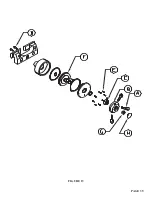
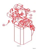
SEE FIGURE 15 ON THE FOLLOWING PAGE.
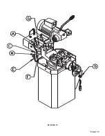
Before powering the machine, the up and down strokes of the saw head must be set. The stroke is set by
the collars (A & B) on the shaft (C).
TO SET THE STROKE:
1. Without powering the saw, cycle the head down by depressing the foot switch, with the ON-OFF
switch in the OFF position. If this switch is in the ON position, the saw motor will start when the
pedal is depressed.
2. Close the flow control (D) down so that the head travels down slowly. When the blade reaches the
point where it will cut through the material, close the flow control valve (D) and the head will stop at
that point.
3. Loosen the handle (E) on the collar (B) and slide the collar up until it contacts the limit switch (F).
4. Slowly release the flow control knob and allow the head to return until the blade is just high enough
that the material will feed under the blade. Then, close the flow control valve.
5. Loosen the handle on the upper collar (A) and slide the collar down until it contacts the limit switch
(G).
6. To make sure that the settings are correct, open the flow control valve (D) and cycle the head several
times before powering the machine.
Ö
CAUTION: ANY TIME THAT THE BLADE OR THE SIZE OF THE MATERIAL BEING CUT IS
CHANGED, THE STROKE OF THE MACHINE HAS TO BE CHECKED. FAILURE TO SET
THE STROKE OF THE MACHINE WILL RESULT IN DAMAGE TO THE MACHINE OR TO
THE BLADES.
7. Adjust the flow control valve (D) to the proper cutting feed rate before cutting any material.
The lubricating device should produce a drop of oil every 5 to 10 cycles. It can be adjusted by the
knob on top of the lubricator. There is a clear plastic dome on top of the lubricator with a copper
tube inside. The oil should drop from the copper tube. The oil in the lubrication device should be
checked everyday. The oil level in the reservoir should be checked every week. For recommended
fluids, REFER TO SECTION 5.2.
As with all other functions of the saw, selection of the proper blade, spindle speed and clamping are
very important in providing a quality finished product.
PAGE 38
Summary of Contents for CPO 350
Page 1: ...CPO 350 VARIABLE SPEED COLD SAW PRINTED SEPTEMBER 2014...
Page 7: ...PAGE 7 FIGURE 1...
Page 8: ...4 2 MACHINE MOVING PROCEDURES SEE FIGURE 2 BELOW PAGE 8 FIGURE 2...
Page 11: ...PAGE 11 350 VS POWER DOWN 230 VOLT SEE PAGE 47 FOR POWER DOWN WIRING FIGURE 3 1...
Page 12: ...PAGE 12 350 VS MANUAL PK 230 VOLT FIGURE 3 2...
Page 13: ...PAGE 13 350 VS POWER DOWN 460 VOLT SEE PAGE 47 FOR POWER DOWN WIRING FIGURE 3 3...
Page 14: ...PAGE 14 350 VS MANUAL PK 460 VOLT FIGURE 3 4...
Page 17: ...PAGE 17 FIGURE 4...
Page 19: ...PAGE 19 FIGURE 5...
Page 27: ...PAGE 27 FIGURE 8 FIGURE 9...
Page 29: ...PAGE 29 FIGURE 10...
Page 33: ...PAGE 33 FIGURE 12...
Page 35: ...PAGE 35 FIGURE 13...
Page 37: ...PAGE 37 FIGURE 14...
Page 39: ...PAGE 39 FIGURE 15...
Page 41: ...PAGE 41 FIGURE 16...
Page 43: ...PAGE 43 FIGURE 17...
Page 45: ...7 2F POWER DOWN FEED WIRING DIAGRAM Ser s 6425 Up PAGE 45 FIGURE 19...
Page 46: ...7 2G PNEUMATIC SCHEMATIC POWER DOWN MACHINES PAGE 46 FIGURE 20...
Page 47: ...THIS PAGE LEFT BLANK INTENTIONALLY PAGE 47...
Page 49: ...PAGE 49 FIGURE 21...
Page 51: ...PAGE 51 FIGURE 22...
Page 55: ...PAGE 55 FIGURE 23...
Page 59: ...PAGE 59 FIGURE 25...
Page 61: ...PAGE 61 FIGURE 26...
Page 63: ...PAGE 63 FIGURE 27...
Page 65: ...PAGE 65 FIGURE 28...
Page 67: ...PAGE 67 FIGURE 29...
Page 69: ...PAGE 69 FIGURE 30...
Page 71: ...PAGE 71 FIGURE 31...
Page 73: ...PAGE 73 FIGURE 32...
Page 75: ...PAGE 75 FIGURE 33...
Page 77: ...PAGE 77 FIGURE 33...
Page 79: ...PAGE 79 FIGURE 34...
Page 81: ...PAGE 81 FIGURE 35...
Page 83: ...PAGE 83 FIGURE 36...
Page 85: ...PAGE 85 FIGURE 37...
Page 87: ...PAGE 87 FIGURE 38...
Page 89: ...PAGE 89 FIGURE 39...
Page 91: ...PAGE 91 FIGURE 40...
Page 93: ...PAGE 93 FIGURE 41...


