2. Always break in the blade before you start normal cutting.
3. Do not apply excessive down pressure on the workpiece. Excessive down pressure will cause the teeth
to remove too large of a chip, resulting in premature dulling or breakage.
4. Use a good quality, synthetic coolant and maintain the proper ratio of coolant to water as
recommended in SECTION 4.7.
5. Have your blades re-sharpened by someone who has the right equipment for circular cold saw blades.
Improper re-sharpening is one of the most common problems encountered in cold sawing.
6. Keep the blade flange, the face of the blade spindle and the blade clean and free from nicks. Any
contamination or nicks on the flange, spindle or the blade will cause the blade to run out of alignment.
7. Always remove the back lash when installing a blade. For instructions, REFER TO SECTION 6.1.
Also, check the condition of the drive pins when replacing the blade. If the drive pins are broken or
worn, replace them.
8. Any of the above problems may cause a condition known as pick-up. Pick-up is caused when small
pieces of the material being cut adhere themselves to the blade. When pick-up is present, you will feel
a jerking or jumping motion in the saw head while cutting. This is caused by the blade being pinched
as it goes through the material where the pick-up is present. Pick-up can be removed by using a fine
honing stone or a very fine file. When removing pick-up, care must be taken not to remove any part
of the blade. After the pick-up has been removed, review the above items to determine what caused
the problem.
8.3 COOLANT SYSTEM
1. IF COOLANT WILL NOT FLOW:
A. Check the wiring connections to the pump and make sure that the pump is running.
B. Check the level of the coolant in the reservoir. If the level is less than 3 inches, the fluid will not flow.
C. Check the reservoir for contamination or sludge build-up that may be blocking the pump inlet.
D. Remove the coolant line from the guard and make sure that it’s clear. Also, make sure that the valve
on the guard is open.
2. IF THE COOLANT PUMP IS LEAKING:
A. Check the connections on the coolant lines.
B. If the pump itself is leaking, there is a seal kit available. For instructions, SEE SECTION 5.4. For
part numbers, SEE SECTION 9.6.
PAGE 53
Summary of Contents for CPO 350
Page 1: ...CPO 350 VARIABLE SPEED COLD SAW PRINTED SEPTEMBER 2014...
Page 7: ...PAGE 7 FIGURE 1...
Page 8: ...4 2 MACHINE MOVING PROCEDURES SEE FIGURE 2 BELOW PAGE 8 FIGURE 2...
Page 11: ...PAGE 11 350 VS POWER DOWN 230 VOLT SEE PAGE 47 FOR POWER DOWN WIRING FIGURE 3 1...
Page 12: ...PAGE 12 350 VS MANUAL PK 230 VOLT FIGURE 3 2...
Page 13: ...PAGE 13 350 VS POWER DOWN 460 VOLT SEE PAGE 47 FOR POWER DOWN WIRING FIGURE 3 3...
Page 14: ...PAGE 14 350 VS MANUAL PK 460 VOLT FIGURE 3 4...
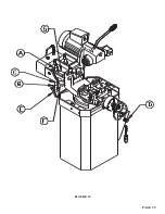
Page 17: ...PAGE 17 FIGURE 4...
Page 19: ...PAGE 19 FIGURE 5...
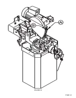
Page 27: ...PAGE 27 FIGURE 8 FIGURE 9...
Page 29: ...PAGE 29 FIGURE 10...
Page 33: ...PAGE 33 FIGURE 12...
Page 35: ...PAGE 35 FIGURE 13...
Page 37: ...PAGE 37 FIGURE 14...
Page 39: ...PAGE 39 FIGURE 15...
Page 41: ...PAGE 41 FIGURE 16...
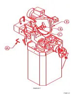
Page 43: ...PAGE 43 FIGURE 17...
Page 45: ...7 2F POWER DOWN FEED WIRING DIAGRAM Ser s 6425 Up PAGE 45 FIGURE 19...
Page 46: ...7 2G PNEUMATIC SCHEMATIC POWER DOWN MACHINES PAGE 46 FIGURE 20...
Page 47: ...THIS PAGE LEFT BLANK INTENTIONALLY PAGE 47...
Page 49: ...PAGE 49 FIGURE 21...
Page 51: ...PAGE 51 FIGURE 22...
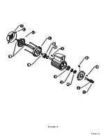
Page 55: ...PAGE 55 FIGURE 23...
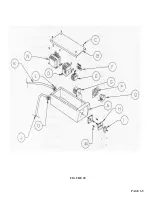
Page 59: ...PAGE 59 FIGURE 25...
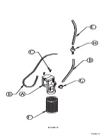
Page 61: ...PAGE 61 FIGURE 26...
Page 63: ...PAGE 63 FIGURE 27...
Page 65: ...PAGE 65 FIGURE 28...
Page 67: ...PAGE 67 FIGURE 29...
Page 69: ...PAGE 69 FIGURE 30...
Page 71: ...PAGE 71 FIGURE 31...
Page 73: ...PAGE 73 FIGURE 32...
Page 75: ...PAGE 75 FIGURE 33...
Page 77: ...PAGE 77 FIGURE 33...
Page 79: ...PAGE 79 FIGURE 34...
Page 81: ...PAGE 81 FIGURE 35...
Page 83: ...PAGE 83 FIGURE 36...
Page 85: ...PAGE 85 FIGURE 37...
Page 87: ...PAGE 87 FIGURE 38...
Page 89: ...PAGE 89 FIGURE 39...
Page 91: ...PAGE 91 FIGURE 40...
Page 93: ...PAGE 93 FIGURE 41...

