PAGE 23
4.6A PUNCH & TOOL STATION
The stroke setting is important for the proper operation of the machine. If this setting has changed,
the machine may over travel and cause the cylinder to "bottom out". This continued condition will
eventually cause the starter overload to open. It can also cause the hydraulic oil to overheat and damage
hydraulic system components. A slight change in the stroke setting can result in inadequate stroke to
operate the tooling. A check of the machine’s stroke setting for the punch and tooling station is made at
the punch station.
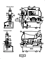
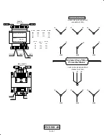
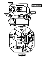
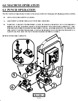
SEE FIGURE 7 ON THE PRECEDING PAGE.
1.
Mounting Plate
2.
Stroke Control Handles (2)
3.
Punch/Tool/Start Selector Switch
5. Metering Boss
6. Mounting Plate Bolts
7. Start Switch
10. Run/Jog Switch
►
PUNCH & TOOL STROKE ADJUSTMENT ◄
1.
Set the stroke control handles (2) out to their farthest position.
2.
Place the disconnect switch in the ON position and both selector switches (3 & 4) in the START
position.
3.
Turn the RUN-JOG switch (10) to the JOG position.
4.
The die holder must be removed and the stripper swung to the side, out of the way.
5.
Power the machine and jog the ram down until it measures 8.19 inches (208mm) from the bolster to
the bottom of the ram.
6.
Turn the machine’s power off.
7.
Check to see if the metering boss (5) has contacted the lower limit switch.
8.
If it has not, loosen the two mounting plate screws (6) and move the mounting plate (1) up until
contact is made.
9.
Tighten the screws and re-check the dimensions. Repeat, if needed.
10. When the ram is in the UP position, the dimension is 10.53 inches (267mm).

