PAGE 24
4.6B NOTCH & SHEAR STATION
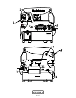
A check of the machine’s stroke setting for shearing and notching is made at the notcher station.
SEE FIGURE 8 ON THE FOLLOWING PAGE.
4.
Shear/Notch/Start Selector Switch
7.
Start Switch
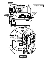
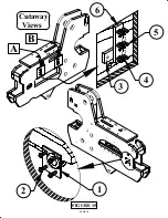
12. Stroke Control Handles (2)
13. Mounting Plate
14. Mounting Plate Bolts
15. Metering Boss
►
NOTCH & SHEAR STROKE ADJUSTMENT ◄
1.
Set the stroke control handles (12) out to their farthest position.
2.
Place the disconnect switch in the ON position and both selector switches (3 & 4) in the
START position and power the machine.
3.
Place the selector switch in the notching position and allow the machine to travel to the end of the
stroke and then, turn the power off.
4.
Measure the distance from the front of the top notcher blade to the top of the lower notcher blade.
The distance should be 1-7/16 inches (36.5mm).
5.
If this dimension is not correct, loosen the mounting plate screws (14) and move the mounting
plate slightly, left or right. Moving the plate left will increase the dimension; moving it right will
decrease it.
6. Tighten the screws and re-check the dimensions. Repeat, if needed.

