PAGE 32
16.
Re-tighten the bolts (2) in the die holder.
17.
Check to be sure of proper alignment. Realign, if necessary.
18.
Return the stripper to the locked position. For stripper adjustment procedures:
SEE PARAGRAPH D BELOW.
19.
Place the disconnect switch in the ON position and the selector switches in the START position.
Power the machine by pressing the green START button.
20.
Place the selector switch in the TOOL position. To be sure that the alignment is correct, jog the
machine several times with the foot switch, without letting the punch come out of the die.
21.
Place the selector switch in the PUNCH position.
B.
KEYED PUNCHES.
This machine is equipped with a keyed punch ram insert. All shaped punches and dies manufactured by
Scotchman are milled for keyed alignment.
►
NOTE: IF YOU DO NOT USE A KEY WITH SHAPED PUNCHES, IT MAY BE HELPFUL TO
HOLD THE BODY OF THE PUNCH WITH A WRENCH WHILE TIGHTENING THE PUNCH
RETAINING NUT. THIS WILL HELP TO KEEP THE PUNCH FROM ROTATING WITH
THE NUT AS IT IS BEING TIGHTENED.
C.
CHECK ALL PUNCHING TOOLS FOR TIGHTNESS.
The punch and die alignment should be checked intermittently during the punching operations. To do
this, bring the punch down so that it enters the die. Turn the machine off. Check and tighten the punch
retaining nut, the set screw holding the die, and the two bolts holding the die holder. Check for equal
clearance between the punch and die. Place the selector switch in the START position and the run/jog
switch in the JOG position and power the machine. Place the selector switch in the TOOL position and
jog the machine several times to be sure of proper alignment. Place the selector switch in the PUNCH
position.
D.
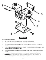
PROPER ADJUSTMENT OF THE STRIPPER:
SEE FIGURE 12 ON THE FOLLOWING PAGE.
To prevent damage to the stripper plate, proper adjustment of the stroke and the height of the stripper
are necessary on this model. The stripper should be adjusted down to approximately 1/8 of an inch
(3 mm) above the material being punched.


