PAGE 36
6.2 BAR SHEAR OPERATION
►
CAUTION: WHEN THE BAR SHEAR STATION IS NOT IN USE, ALWAYS CRANK THE
HOLD-DOWN DEVICE TO ITS DOWN POSITION.
When using the bar shear on your Scotchman Ironworker, always use the hold-down device. Never put
any part of your body between the hold-down and the material to be sheared. A clearance of 1/8 inch
(3 mm) between the hold-down and the material to be sheared is acceptable. The maximum tonnage
available on the bar shear is to the right, or closest to the pivot point. For applications that do not require
the maximum tonnage, move the material to the left for minimal distortion of the drop-off piece. Do not
attempt to shear pieces that are too short for the hold-down to grip as this will cause the material to
"kick-up" and result in a poor quality cut and possible damage to the machine. The maximum sized
material that can be sheared is 1 x 12 inch (25 x 305mm) mild steel.
This is WITH the Saber Blade (upper
blade) which IS standard equipment for this machine. Consult dealer or factory for details if needed.
THE BASIC METHOD OF OPERATING THE BAR SHEAR CONSISTS OF FIVE STEPS.
1.
Place the disconnect switch in the ON position and both selector switches in the START position
and power the machine.
2.
Place the selector switch in the SHEAR position.
3.
Place the material to be sheared between the shear blades.
4.
CRANK THE HOLD-DOWN DEVICE DOWN UNTIL IT CONTACTS THE MATERIAL TO
BE SHEARED. This prevents "kick-up" of the work piece and possible damage to the shear blades.
5.
DEPRESS THE FOOT PEDAL. Keep hands clear of all moving parts.
Lubricating oil should be applied to the blades every 10 to 15 cuts. In addition to the above five basic
steps of operation, the operator should also be familiar with the following:
A.
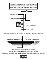
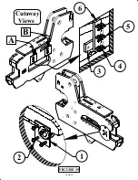
MAINTAIN PROPER BLADE CLEARANCE.
The quality of the cut is an immediate indication of the condition of the shear blades, the amount of
clearance between the blades, or the amount of "spring-back" in the shear arm. Only the bottom shear
blade is symmetrical and can be rotated to expose up to four (4) cutting edges. The top blade is slightly
curved on the cutting side and has only (2) cutting edges. For blade clearance recommendations, see
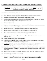
Figure 14 on the following page. For adjustment procedures, REFER TO SECTIONS 6.2A AND 6.2B.
B.
ALL CUTS SHOULD BE MADE AS FAR FROM THE ARM PIVOT AS POWER WILL PERMIT.
The shear blades should contact the work piece as flat as possible, to reduce to a minimum the amount of
"curl" on the drop-off piece. More shearing force is obtained as the operator moves the work-piece to the
right. The machine is designed to shear mild steel rated at 65,000 PSI tensile strength.


