PAGE 49
7.2A ROD SHEAR INSTALLATION
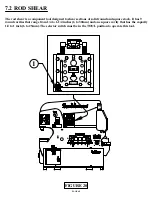
SEE FIGURE 20 ON THE PRECEDING PAGE.
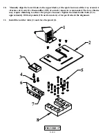
The rod shear mounts in the tool station under the upper arm and is held in place with the finger clamps
(1) provided.
Since the rod shear requires a short stroke, (approximately 1/2 inch (12mm) and has no slug, it can be
operated at any practical location under the upper arm. Care must be taken to align the pressure block
of the tool squarely under the upper arm.
►
CAUTION: TO PREVENT DAMAGE TO THE TOOL, THE STROKE OF THE MACHINE
MUST BE SET WHEN USING THE ROD SHEAR.
Set the upstroke of the machine so that the workpiece easily slides through the tool. Set the down stroke
so that the cut can be made with a minimum amount of stroke.
Failure to set the stroke of the machine will damage the tool.
7.2B ROD SHEAR OPERATION
Oil the blades before starting and every 10 to 15 cuts, thereafter. Grease the slider block between the tool
and the arm every two hours of operation. On all round sizes, select the proper cavity for the size being
sheared. In the square cavity, there is a kick-up bolt adjustment. Adjust this bolt so that the workpiece
will just feed under the bolt and remains horizontal to the shear.
►
CAUTION: WHEN SHEARING SHORT PIECES OR NIPPING THE ENDS OF THE ROD,
CARE SHOULD BE TAKEN SO THAT THE SLUGS DO NOT BUILD UP IN THE DROP-OFF
SIDE. IF THIS HAPPENS, THERE IS A POSSIBILITY OF INJURY TO OTHER PERSONNEL
AND DAMAGE TO THE TOOL. ALWAYS REMOVE THE ROD SHEAR WHEN IT IS NOT
IN USE.
026278
026775
026776
026283
026283
201110
M6x12
201235
M10x80
026779
201415
M12x40
026746
026746
221210
M10 x 25
221210
M10 x 25
204225
M10 x 60
204225
M10 x 60
026744 Rod Shear
Complete Tool
220016
201215
M10x40
201215
M10x40
201215
M10x40
201215
M10x40
203235
M10x90
203235
M10x90
203235
M10x90
203235
M10x90
203235
M10x90
203235
M10x90


