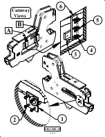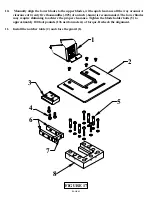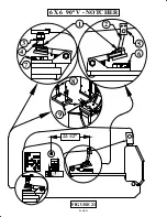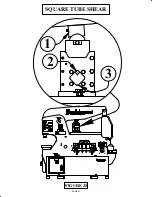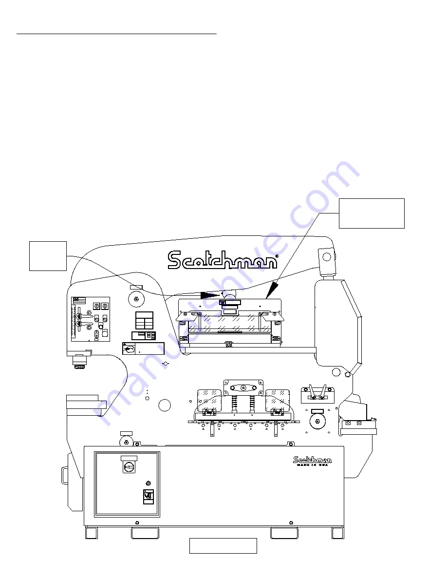
FIGURE 22
7.4B BRAKE OPERATION
NEVER PUT YOUR HANDS INTO OR AROUND A BRAKE WHILE IT IS IN OPERATION.
Hold short pieces with tongs or a similar device. When using the brake, it is necessary to load the brake
centrally. (Visual centering is sufficient.) If work is performed off-center, the guide pins could be
damaged. The brake lift is provided by springs. If sticking occurs at the bottom of the stroke and the
upper die does not return, a slight tap on the upper die is usually sufficient to free the guides.
DO NOT ATTEMPT TO FREE THE BRAKE BY HAND.
Sticking can be caused by lack of lubrication, complexity of the part being bent or bent guide pins.
Keep the guides well lubricated and replace them, if damaged. It is common practice to have the
bottom die opening 8 times the thickness of the material being bent. If the parts require a bend of
less than 90 degrees, adjust the down stroke of the machine until the desired bend is obtained. A
great variety of standard brake dies can be used with this unit. These are available from Scotchman
Industries or brake die suppliers.
ALWAYS REMOVE THE TOOL WHEN IT IS NOT IN USE.
Slider
Block
24" Brake
Shown
037003 Assy
4185
013180
13179
201110
M6x12
201110
M6x12
201110
M6x12
201110
M6x12
013180
13179
201110
M6x12
201110
M6x12
201110
M6x12
201110
M6x12
17341
080435 Assy.
080430
230210
230210
13220 - 3ph 13225 - 1ph
230 Volts
19121
OFF
EATON
11856
ELECTRICAL HAZARD
Turn off power
and lock out
before servicing.
DANGER
3122
1213
25525 Raw
224205
224205
33176
80155
080174
243101
Assy.
13190
080061
080061
WARNING
SAFETY GLASSES REQUIRED WHEN
OPERATING OR OBSERVING THIS MACHINE
NEVER-
NEVER-
NEVER-
NEVER-
NEVER-
NEVER-
NEVER-
TO PREVENT SERIOUS BODILY INJURY
Operate, install tooling, service or adjust machine without
operator's manual and safety film.
Service machine with electrical power connected.
Operate any station without the respective strippers or
Operate machine with protective guards removed.
Place any part of your body under blade, punch or moving
Operate punch station without checking the punch to die
alignment and tightness.
Punch half holes, punch or shear unknown materials, side load
DO NOT REMOVE THIS SIGN FROM THIS MACHINE
REV. 0310
FOR MORE INFORMATION CONTACT SCOTCHMAN INDUSTRIES INC.
1-800-843-8844
003100
proper instructions and without reading and understanding the
hold-downs in place.
members.
(Check alignment and tightness daily.)
press brakes.
AT
SERIAL
SCOTCHMAN INDUSTRIES, INC.
PHILIP, SOUTH DAKOTA, U.S.A.
MADE IN U.S.A.
MODEL
FLA
HZ
PH
H.P.
VOLT
BLADE LENGTH
PH. 605-859-2542
PSI
33149
010117
80191
80211
80197
33018
80424 F
33157
13268
224205
224205
224205
224205
080174
243101
Assy.
080174
243101
Assy.
80156 Sales
LUBRICATE
BEFORE
OPERATING
19103
0481
LUBRICATE
BEFORE
OPERATING
19103
0481
LUBRICATE
BEFORE
OPERATING
19103
0481
JOG
3200
STOP
START
START
RUN JOG
PUNCH
TOOL
RUN PROBE
SHEAR
NOTCH
START
MM.
IN.
MM.
IN.
90
80
70
60
50
40
30
20
10
10
90
80
70
60
50
40
30
20
3
2
1
3
2
1
0
004085
213012
213012
201240
201240
033707
080061
080061
80860
16362
16346
26303 - Brake
LUBRICATE
BEFORE
OPERATING
19103
0481
REMOVE TOOL WHEN NOT IN USE
AND/OR DAMAGE TO MACHINE
TO PREVENT SERIOUS BODILY INJURY
003145
WARNING
TO PREVENT SERIOUS BODILY INJURY
AND/OR DAMAGE TO MACHINE
DO NOT BRAKE ROUNDS
LOAD MATERIAL CENTRALLY
0398
003150
#037009
11,04
DUAL OPERATOR
150/240 - 24M
MACHINE CAPACITIES
SPEC. BASED ON MILD STEEL-65,000 PSI TENSILE
PUNCH
150 TONS
Ø47 THRU 25MM
Ø1-7/8 THRU 1.0"
FLAT SHEAR
1 X 14" - 3/4 X 24"
BLADE LENGTH 24" - 600MM
25X300 - 12X600MM
THROAT DEPTH
12" - 305MM
RECT. NOTCHER
76X127X12MM
3"X5"X1/2"
PUNCH STROKE
2.25" - 57MM
ANGLE SHEAR
150X150X12MM
6"X6"X1/2"
PAGE 53

