background image

PAGE 6

1.0 INTRODUCTION

2.0 SAFETY PRECAUTIONS

1.

The operators of this machine must be qualified and well trained in the operation of the machine.

           The operators must be aware of the capacities of the machine and the proper use of the hold down
           device, strippers and guards provided with the machine. This manual is not intended to teach
           untrained personnel how to operate machinery.

2.

All of the guards, adjustable restrictors and awareness barriers must be installed on the machine

           and kept in good working order. Promptly replace worn or damaged parts with authorized parts.
3.

Never place any part of your body into or under any of the machine’s moving parts, strippers or

           hold devices.

4.

Wear the appropriate personal protective equipment. Safety glasses are required at all times,

           whether operating, setting up or observing this machine in operation. Since heavy pieces of metal
           with sharp edges can be processed on this machine, the operator should also wear steel-toed shoes
           and leather gloves.

5.

Strictly comply with all warning labels and decals on the machine. Never remove any of the labels

           and replace worn or damaged labels promptly.

6.

Always disconnect and lock out the power when performing maintenance work or setting up any

           tooling on the machine. Follow the procedures outlined in the operator’s manual for setting up,
           changing or aligning any tooling on this machine.

7.

Never operate this machine with dull or damaged tooling. Replace worn punches, dies and blades

           promptly.

PAGE 6

The Scotchman DO-150/240-24M is a versatile, multi-purpose, shearing, punching and forming machine

engineered for trouble-free operation. The design of the machine combines simplicity of operation with

smooth, full stroke control. The ability of the operators to control the machine’s direction of movement

at any point in the stroke (stop, jog or reverse) gives the Scotchman Ironworker a tremendous advantage

over mechanical Ironworkers. There is no chance of the Scotchman being "accidentally tripped".

The hydraulic system operates at a maximum pressure of 3,500 PSI (241 BAR) in the punch and tooling

station and 3,500 PSI (241 BAR) in the shear and notch position and is protected from overload by a

relief valve. The Scotchman DO-150/240-24M is designed as a dual operator Ironworker. On this model,

the punch and tooling stations operate independently of the shear and notcher stations.

This machine is designed for the user that wants the advantage of doubling production by having two

operators using the same machine at the same time. Scotchman also offers many optional tools that are

adaptable to this model. Some of the optional tools available are: a channel shear, pipe notcher, 12 & 24

inch brake attachments, a picket tool and a variety of special tools. If you have a special application,

please contact your dealer or the factory.

Summary of Contents for DO-150-24M

Page 1: ...punch station without checking the punch to die alignment and tightness Punch half holes punch or shear unknown materials side load DO NOT REMOVE THIS SIGN FROM THIS MACHINE REV 0310 FOR MORE INFORMA...

Page 2: ...www scotchman com MODEL DO 150 240 24M IRONWORKER SCOTCHMAN INDS 180 E US HWY 14 PO BOX 850 PHILIP SD 57567 Call 1 800 843 8844 VERSION 5 SEPTEMBER 2021...

Page 3: ...unknown materials side load DO NOT REMOVE THIS SIGN FROM THIS MACHINE REV 0310 FOR MORE INFORMATION CONTACT SCOTCHMAN INDUSTRIES INC 1 800 843 8844 003100 proper instructions and without reading and...

Page 4: ...Tool Station Notch and Shear Station MAINTENANCE Lubrication Scheduled Maintenance MACHINE OPERATION Punch Operation Bar Shear Operation Shear Arm Adjustment Shear Blade Adjustment Rectangle Notcher...

Page 5: ...t Fence Tool Operation Square Tube Shear Square Tube Shear Installation Square Tube Shear Operation Optional Die Holders Punch Retaining Nuts Offset Die Holder for Flange Punching 2 1 2 x 3 Inch Die H...

Page 6: ...ipper Assembly Upper Arm Assembly Punch Cylinder Upper Stroke Control Assembly Shear Notcher Stroke Hold Down Assembly Slug Buckets Fan E Stop Sheet Metal Parts Hardware Power Unit Electrical Unit Not...

Page 7: ...ual for setting up changing or aligning any tooling on this machine 7 Never operate this machine with dull or damaged tooling Replace worn punches dies and blades promptly PAGE 6 The Scotchman DO 150...

Page 8: ...O B the factory or refund the purchase price for any goods which are defective in materials or workmanship provided the buyer returns the warranty registration card within thirty 30 days of the purcha...

Page 9: ...cker 8 1 010117 27 Scotchman Decal 9 1 019102 Decal Reservoir Capacity not Shown 10 6 019103 Decal Lubricate 11 9 019105 Decal Grease Point 12 1 019127 US Flag Decal 13 1 037009 DO 150 CAPACITY DECAL...

Page 10: ...trippers or Operate machine with protective guards removed Place any part of your body under blade punch or moving Operate punch station without checking the punch to die alignment and tightness Punch...

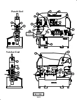
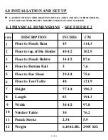
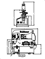
Page 11: ...114 3 2 Floor to top of Die Holder 40 1 2 102 9 3 4 5 6 7 8 9 10 Floor to Punch Bolster 34 1 2 87 6 Floor to Bar Shear 29 3 4 75 6 Floor to Tool Table 48 121 9 Height 77 1 4 196 2 Length 83 194 3 Punc...

Page 12: ...reading and understanding the hold downs in place members Check alignment and tightness daily press brakes AT SERIAL SCOTCHMAN INDUSTRIES INC PHILIP SOUTH DAKOTA U S A MADE IN U S A MODEL FLA HZ PH H...

Page 13: ...Punch half holes punch or shear unknown materials side load DO NOT REMOVE THIS SIGN FROM THIS MACHINE REV 0310 FOR MORE INFORMATION CONTACT SCOTCHMAN INDUSTRIES INC 1 800 843 8844 003100 proper instr...

Page 14: ...te any station without the respective strippers or Operate machine with protective guards removed Place any part of your body under blade punch or moving Operate punch station without checking the pun...

Page 15: ...amages CHECK SPECIFICALLY THE FOLLOWING ITEMS 1 The stroke control handles 2 The jog switch 3 The selector switch 4 The emergency stop buttons 5 Hydraulic hoses and fittings 6 A general inspection of...

Page 16: ...diagram for the machine is inside the cover of the control box THE DIAGRAM IS ALSO IN SECTION 11 AT THE END OF THIS MANUAL For electrical supply lines ten feet 3 m or shorter we recommend at least 12...

Page 17: ...H RESET TEST NC 22 14 NO NO NC 97 96 98 95 _OL_ ZB32 32 2 6 A 4 8 OVERLOAD TO MOTOR L1 L2 L3 T1 T2 T3 DISCONNECT 2 T1 4 T2 6 T3 1 L1 3 L2 5 L3 A1 A2 14 NO 13 NO 1M SINGLE PHASE INCOMING POWER 1 L1 3 L...

Page 18: ...40 380 400 415 440 460 480 575 600 H1 H2 H1 H3 XF X2 120 130 110 115 120 85 91 100 110 FUSE FUSE 208 220 230 500 550 H1 H4 H1 H5 XF X4 XF X3 125 95 99 EATON CO250E6U X4 X3 X2 X1 XF H5 H4 H3 H2 H1 1T 3...

Page 19: ...This is the jog control It only operates when the RUN JOG selector switch 2 is in the JOG position FIGURE 5 PAGE 18 4 6 8 3 5 2 1 230 Volts 19121 OFF EATON 11856 ELECTRICAL HAZARD Turn off power and l...

Page 20: ...extend and the punch to close CAUTION WHENEVER YOU ARE USING THE PUNCH STATION REMOVE ALL TOOLS FROM THE TOOL TABLE AREA WHEN USING THE TOOL TABLE AREA REMOVE THE PUNCH AND DIE FROM THE PUNCH STATION...

Page 21: ...NING SAFETY GLASSES REQUIRED WHEN OPERATING OR OBSERVING THIS MACHINE NEVER NEVER NEVER NEVER NEVER NEVER NEVER TO PREVENT SERIOUS BODILY INJURY Operate install tooling service or adjust machine witho...

Page 22: ...power and lock out before servicing DANGER 3122 1213 7 SHEAR NOTCH START RUN JOG RUN PROBE STOP START TOOL PUNCH START JOG3200 7711 Sales Painted Cover 33707 Complete Assy MM IN MM IN 90 80 70 60 50 4...

Page 23: ...your body under blade punch or moving Operate punch station without checking the punch to die alignment and tightness Punch half holes punch or shear unknown materials side load DO NOT REMOVE THIS SIG...

Page 24: ...etering Boss 6 Mounting Plate Bolts 7 Start Switch 10 Run Jog Switch PUNCH TOOL STROKE ADJUSTMENT 1 Set the stroke control handles 2 out to their farthest position 2 Place the disconnect switch in the...

Page 25: ...position and both selector switches 3 4 in the START position and power the machine 3 Place the selector switch in the notching position and allow the machine to travel to the end of the stroke and t...

Page 26: ...ade punch or moving Operate punch station without checking the punch to die alignment and tightness Punch half holes punch or shear unknown materials side load DO NOT REMOVE THIS SIGN FROM THIS MACHIN...

Page 27: ...on with a brush or applied with a squirt can or a spray applicator Grease the punch ram bushing 1 and the main pins 2 3 4 daily Grease all other fittings twice per week To gain access to the two punch...

Page 28: ...out the respective strippers or Operate machine with protective guards removed Place any part of your body under blade punch or moving Operate punch station without checking the punch to die alignment...

Page 29: ...he mounting bolts in the punch ram bushing Make sure that they are tight Also check the bolt that runs through the punch ram straps to make sure that it s not so tight that the straps are binding on t...

Page 30: ...e with electrical power connected Operate any station without the respective strippers or Operate machine with protective guards removed Place any part of your body under blade punch or moving Operate...

Page 31: ...RENCE IF YOU DID NOT RECEIVE A SAFETY CD PLEASE CONTACT YOUR DEALER OR THE FACTORY REFER TO FIGURE 11 BELOW 243101 016095 1 2 3 4 5 204220 M10x30 2190 60 6 0 1 2 3 1 2 3 10 30 40 50 60 70 80 20 90 10...

Page 32: ...tch in the TOOL position and allow the cylinder to completely extend 9 Turn the machine s power off 10 Select the proper punch and die Make sure that there is proper clearance between the punch and di...

Page 33: ...TIGHTENING THE PUNCH RETAINING NUT THIS WILL HELP TO KEEP THE PUNCH FROM ROTATING WITH THE NUT AS IT IS BEING TIGHTENED C CHECK ALL PUNCHING TOOLS FOR TIGHTNESS The punch and die alignment should be c...

Page 34: ...per install the plate 4 on the bottom of the stripper 4 For maximum visibility and safety always adjust the stripper down as close to the material as possible CAUTION TO PREVENT PUNCH BREAKAGE ON THE...

Page 35: ...THIN RATED PUNCHING CAPACITIES This machine is designed to operate in mild steel Within conservative limits it can also operate in medium carbon annealed steel and some forms of abrasion resistant ste...

Page 36: ...23 8 19 7 22 0 24 6 26 9 29 5 31 8 33 7 36 9 39 9 44 3 47 7 30 8 HOLE DIAMETER METAL GAUGE THICKNESS INCHES 3 16 1875 1 4 250 5 16 3125 3 8 375 7 16 4375 1 2 500 9 16 5625 5 8 625 11 16 6875 3 4 750 1...

Page 37: ...he machine 2 Place the selector switch in the SHEAR position 3 Place the material to be sheared between the shear blades 4 CRANK THE HOLD DOWN DEVICE DOWN UNTIL IT CONTACTS THE MATERIAL TO BE SHEARED...

Page 38: ...8 5 8 75 1 0 1 2 3 8 MATERIAL THICKNESS in 022 018 026 026 020 030 017 012 022 013 010 017 009 007 012 BLADE CLEARANCE in 218120 218120 LOWER BLADE CLEARANCE UPPER BLADE 1 2 CANT Blade clearance is fa...

Page 39: ...4 Tighten all four adjusting screws on the pressure plate so that they are snug and will force the shear arm solidly against the rear frame Excessive tightening of these screws only increases wear 5 S...

Page 40: ...0122 0 M10x 50 2181 12 21811 2 1 2 5 3 4 Cutaway Views 6 080174 Grease Bolt 201610 243101 210014 M12 Jam 218120 210014 M12 Jam 218120 210014 M12 Jam 218120 210014 M12 Jam 218120 0 8 0 1 7 4 G r e a s...

Page 41: ...djusting screws 1 about 1 8 of a turn past resistance 10 Tighten the bolts 2 to 1 4 a turn past resistance 11 Adjust the lower adjusting screws 1 up to the blade and then tighten all of the bolts star...

Page 42: ...2 6 M 1 6 x 6 5 2 2 1 4 2 6 M 1 6 x 6 5 2 2 1 4 2 6 M 1 6 x 6 5 2 2 1 4 2 6 M 1 6 x 6 5 2 2 1 4 2 6 M 1 6 x 6 5 2 1 8 1 2 0 2 1 8 1 2 0 2 1 8 1 2 0 2 1 8 1 2 0 2 1 8 1 2 0 2 1 8 1 2 0 2 1 8 1 2 0 2 1...

Page 43: ...e top blade 3 is parallel with the bolster TURN THE MACHINE S POWER OFF 9 Replace the lower blade holder 8 with the blades 6 7 installed Start the mounting bolts 5 DO NOT TIGHTEN This tool is operated...

Page 44: ...e holder bolts 5 to approximately 100 foot pounds 136 newton meters of torque Recheck the alignment 11 Install the notcher table 2 and close the guard 1 1 3 4 7 5 8 212014 212014 212014 212014 212014...

Page 45: ...strippers or Operate machine with protective guards removed Place any part of your body under blade punch or moving Operate punch station without checking the punch to die alignment and tightness Pun...

Page 46: ...enough to slide the workpiece freely through the unit The lower stroke should be set so that the upper blade point enters the lower blades approximately 1 8 inch 3mm 7 1B 6 X 6 ANGLE SHEAR OPERATION...

Page 47: ...ody under blade punch or moving Operate punch station without checking the punch to die alignment and tightness Punch half holes punch or shear unknown materials side load DO NOT REMOVE THIS SIGN FROM...

Page 48: ...X 3 X 1 4 OO3195 0502 BEYOND THIS GUARD DO NOT PL ACE FINGERS BODILY INJURY TO PR EVENT SE RIOUS WARNING 00314 0 201212 M10x35 221220 M10 X 40 221220 M10 X 40 221220 M10 X 40 221220 M10 X 40 2 REST BU...

Page 49: ...tructions and without reading and understanding the hold downs in place members Check alignment and tightness daily press brakes AT SERIAL SCOTCHMAN INDUSTRIES INC PHILIP SOUTH DAKOTA U S A MADE IN U...

Page 50: ...fore starting and every 10 to 15 cuts thereafter Grease the slider block between the tool and the arm every two hours of operation On all round sizes select the proper cavity for the size being sheare...

Page 51: ...CHINE FAILURE TO SET THE STROKE CONTROLS WILL RESULT IN DAMAGE TO THE TOOL AND POSSIBLE INJURY TO THE OPERATOR The pusher is attached to notcher by the notcher clip 1 and the pusher assembly should be...

Page 52: ...wn materials side load DO NOT REMOVE THIS SIGN FROM THIS MACHINE REV 0310 FOR MORE INFORMATION CONTACT SCOTCHMAN INDUSTRIES INC 1 800 843 8844 003100 proper instructions and without reading and unders...

Page 53: ...nd to check blade alignment After alignment tighten the back up set screws to make sure that the upper blade does not move 7 4 12 24 INCH BRAKES Brakes are component tools designed to bend and form mi...

Page 54: ...oling service or adjust machine without operator s manual and safety film Service machine with electrical power connected Operate any station without the respective strippers or Operate machine with p...

Page 55: ...0 5 6 2 9 6 8 10 1 4 5 2 7 1 6 3 6 6 0 2 2 1 4 OF METAL THICKNESS GAUGE INCHES 5 16 3 8 5 8 1 2 CHROME MOLYBDENUM 100 MORE THAN STEEL STAINLESS STEEL 50 MORE THAN STEEL SOFT ALUMINUM 50 OF PRESSURE LI...

Page 56: ...O PREVENT SERIOUS BODILY INJURY 003145 WARNING TO PREVENT SERIOUS BODILY INJURY AND OR DAMAGE TO MACHINE DO NOT BRAKE ROUNDS LOAD MATERIAL CENTRALLY 0398 003150 026303 24 BRAKE W 2 DIES 026375 V NOTCH...

Page 57: ...e in the PUNCH position to operate this tool The die holder punch retaining nut and the stripper must be removed to install this tool Mount the tool so that it lines up directly under the punch ram an...

Page 58: ...tanding the hold downs in place members Check alignment and tightness daily press brakes AT SERIAL SCOTCHMAN INDUSTRIES INC PHILIP SOUTH DAKOTA U S A MADE IN U S A MODEL FLA HZ PH H P VOLT BLADE LENGT...

Page 59: ...after Grease the slider block between the tool and the arm every two hours of operation The following are BASIC STEPS IN SHEARING WITH THE CHANNEL SHEAR A ADJUST BOTH THE MOVING AND STATIONARY SIDE BL...

Page 60: ...CHER 76X127X12MM 3 X5 X1 2 PUNCH STROKE 2 25 57MM ANGLE SHEAR 150X150X12MM 6 X6 X1 2 Upper Blade Assy Front Side of Upper Blade Rear Side of Upper Blade 26433 160030 160030 016118 016118 016118 016118...

Page 61: ...vertical blades are symmetrical and can be turned to present four 4 cutting edges Clearance between the upper and lower blades is changed by the addition or removal of shims A clearance of twenty thou...

Page 62: ...12x50 201420 M12x50 016185 201420 M12x50 201420 M12x50 201420 M12x50 016184 201420 M12x50 201420 M12x50 201420 M12x50 026431 203212 M10 x 30 203225 M10 x 65 203225 M10 x 65 026431 203212 M10 x 30 2032...

Page 63: ...SING THIS TOOL ALWAYS WEAR SAFETY GLASSES Before operation lubricate the sides and back of the upper die with way oil Repeat this lubrication once daily Cutting blades should be lubricated with a cutt...

Page 64: ...ding and understanding the hold downs in place members Check alignment and tightness daily press brakes AT SERIAL SCOTCHMAN INDUSTRIES INC PHILIP SOUTH DAKOTA U S A MADE IN U S A MODEL FLA HZ PH H P V...

Page 65: ...N THE DOWNSTROKE OF THE MACHINE MUST BE SET BEFORE OPERATING THIS TOOL FAILURE TO SET THE DOWNSTROKE OF THE MACHINE WILL RESULT IN DAMAGE TO THE TOOL AND POSSIBLE INJURY TO PERSONNEL 1 Rotate the tube...

Page 66: ...T MM IN MM IN 90 80 70 60 50 40 30 20 10 10 90 80 70 60 50 40 30 20 3 2 1 3 2 1 0 004085 213012 213012 201240 201240 033707 080061 080061 16096 80831 16096 80831 001280 001275 1272 001167 1165 221005...

Page 67: ...amps Lubricate the pressure block 1 before installing the tool and after every two hours of operation via grease zerk Make sure tool is mounted squarely securely under the beam Set the upstroke of the...

Page 68: ...REV 0310 FOR MORE INFORMATION CONTACT SCOTCHMAN INDUSTRIES INC 1 800 843 8844 003100 proper instructions and without reading and understanding the hold downs in place members Check alignment and tight...

Page 69: ...FFSET DIE HOLDER MUST BE REMOVED WHEN IT IS NOT IN USE FOR SIZES AND APPLICATION SEE THE TOOLING PARTS MANUAL Always follow the preferred method of aligning punches and dies SEE SECTION 6 1 The 2 1 2...

Page 70: ...NG OFFSET DIE HOLDER AND OR DAMAGE TO MACHINE TO PREVENT SERIOUS BODILY INJURY 003 135 DO NOT EXCEED 40 TONS REMOVE TOOL WHEN NOT IN USE AND OR DAMAGE TO MACHINE TO PREVENT SERIOUS BODILY INJURY 003 1...

Page 71: ...punching applications FOR REQUIREMENTS SEE THE 40 TOOLING PARTS MANUAL 7 10E HEAVY DUTY SPLIT RING RETAINING NUT SEE FIGURE 30 BELOW 1 Remove the six socket head cap screws 1 2 Slide the retaining nu...

Page 72: ...1313 26306 201210 201210 201210 201210 203217 203217 203217 243101 026350 Assy 1309 1302 243101 243101 026350 SQUARE TUBE SHEAR 26500 026500 HEAVY DUTY RETAINING NUT punch not included PAGE 71...

Page 73: ...d to the main tube loosen the set screw 4 and slide the probe in as close the bottom shear blade as possible 5 On some models the probe will reach the lower shear blade On these models lock the set sc...

Page 74: ...Item Parts List 025603 Deluxe Back Gauge 48 FIGURE 31 PROBE SHEAR BLADE FLAT STEEL ANGLE IRON ANGLE IRON PROBE PROBE PROBE PLACEMENT BACK GAGE MOUNTING 25311 25314 253 17 As sy 253 20 253 324 253 61 2...

Page 75: ...unit particular attention must be paid when setting the stroke length The stripper unit moves in conjunction with the punch and extra care must be taken by the operator Refer to the setting and operat...

Page 76: ...nch ram When using keyed punches after you start the nut on the ram raise the punch and rotate it until the key seats in the punch ram 17 Use a wrench to tighten the punch retaining nut Make sure that...

Page 77: ...IGURE 32 The springs should be checked periodically A sure sign of over stroking is cracking or splitting of the springs 1 Secure the unit in a vise by clamping the bottom plate 14 Loosen and remove b...

Page 78: ...20 M8 x 25 2545 2 08019 1 2545 2 080191 2545 2 080191 8021 5 2545 2 080191 2545 2 080191 26038 113017 201620 M16x55 113017 201620 M16x55 006262 006202 204220 M10x30 254 50 SLIDE 1 9 PUNCH RAM 220014 2...

Page 79: ...THE WIRING DIAGRAM SEE SECTION 10 6 Check the line voltage at the starter If the correct line voltage is present at the starter either the starter or the motor is defective Contact your local dealer...

Page 80: ...off at the disconnect switch Remove the cover on the foot pedal and check for any loose connections B Make sure that the switches are adjusted properly You should hear two distinct clicks approximate...

Page 81: ...e the limit switches Try the machine again 4 Check the fuses in the control box There are two fuses on the primary side of the transformer and one on the secondary side Remove the fuses and check them...

Page 82: ...y While depressing the foot switch use a pencil or similar device and depress the limit switch that the metering boss is traveling towards If the machine does not stop when the switch is depressed the...

Page 83: ...unknown materials side load DO NOT REMOVE THIS SIGN FROM THIS MACHINE REV 0310 FOR MORE INFORMATION CONTACT SCOTCHMAN INDUSTRIES INC 1 800 843 8844 003100 proper instructions and without reading and...

Page 84: ...other After manually shifting the spool turn the machine on and try it again If the machine now operates the hydraulic oil and the filter should be changed 2 A DEFECTIVE COIL ON THE CONTROL VALVE The...

Page 85: ...g nut on the shaft to 100 foot pounds To prevent the nut from working loose after the cylinder has been reassembled rivet the threads on the end of the ram with a chisel or punch 10 Stand the cylinder...

Page 86: ...PAGE 85 FIGURE 33 3 1 2 4 5 3 1 CLEVIS DO 150 SEAL KITS PUNCH CYL 034305 DO150 CYLINDER SEAL KIT SHEAR CYL 080375 MULTI 6 CYL SEAL KIT...

Page 87: ...UPPER ARM 2 080155 M16 LOCK WASHER 2 212016 GREASE BOLT M16 X 25MM 1 080174 PRESSURE PLATE 016625 2 1 2 SNAP RING 2 004109 SHEAR ARM RUB BLOCK 2 006015 RUB BLOCK 6 201432 M12 X 80MM HHCS 218122 M12 X...

Page 88: ...x70 221435 M16x90 221435 M16x90 221435 M16x90 221435 M16x90 221435 M16x90 214016 214016 214016 214016 214016 033 175 422 071 221322 M12x60 221322 M12x60 221322 M12x60 221322 M12x60 214014 214014 21401...

Page 89: ...body under blade punch or moving Operate punch station without checking the punch to die alignment and tightness Punch half holes punch or shear unknown materials side load DO NOT REMOVE THIS SIGN FR...

Page 90: ...l 006190 11 10 9 03059 5 1513 5 016625 016625 016 063 016 063 01662 0 01662 0 033199 03320 3 080174 Grease Bolt 201610 243101 03320 4 00617 2 03314 8 Ring 03314 7 raw 03314 4 assy 9 37006 080174 Greas...

Page 91: ...M NUT 1 PUNCH RAM 8 010239 PUNCH RAM W INSERT INCLUDES 12 14 15 16 17 18 19 20 2 080211 3 1 2 PUNCH HOLDER 1 221120 M8 X 25 SHCS 1 141010 3 16 X 1 2 ROLL PIN 3 080133 INSERT W KEY INC 16 17 18 1 00412...

Page 92: ...M8 x 25 221120 M8 x 25 221120 M8 x 25 0150 30 4123 221315 M12x40 221315 M12x40 221315 M12x40 221315 M12x40 080210 141010 141010 212014 212014 212014 212014 802 15 0801 91 080210 243101 P N 010239 Kit...

Page 93: ...INISHED 3 230110 M8 X 20 FSHCS 1 080182 M5 ALLEN WRENCH 1 037107 DO135 150 PUNCH TABLE 2 080063 RS JIG HANDLE 2 214014 M12 WASHER 1 219060 M10 X 50 FP SET SCREW 1 204220 M10 X 30 HHCS 1 4 113017 1 3 4...

Page 94: ...26618 026618 37105 37110 204220 M10x30 21906 0 218058 218058 11301 7 113017 204220 M10x30 077145 113017 11301 7 204220 M10x30 37115 37120 80424 22142 0 M1 6x5 0 22142 0 M1 6x5 0 221 420 M1 6x5 0 22142...

Page 95: ...DJ SCREW STRIPPER RIGHT 1 007241 STRIPPER SPRING 2 007240 SPRING RETAINER 2 110014 1 2 13 JAM NUT 1 001541 BALL SPRING SCREW 1 014229 STRIPPER ASS Y 007252 STRIPPER PLATE ITEM QTY PART DESCRIPTION 8A...

Page 96: ...4 1 2 1 3 UNC 230007 230007 007 241 007239 007 244 F R O N T 14229 Assy 7225 Paint ed 7227 Ra w 14228 Sales 1 5 7 8 9 13 18 15 17 0072 52 11741 6 660255 660255 2 4 11 10 16 11740 007240 007236 007229...

Page 97: ...machine with protective guards removed Place any part of your body under blade punch or moving Operate punch station without checking the punch to die alignment and tightness Punch half holes punch or...

Page 98: ...8 0 1 9 5 80196 DO 150 UPPER ARM ASSEMBLY PAGE 97 FIGURE 39 033131 12070 33205 80200 080169 015134 006190 0160 63 0160 63 80155 2 3 4 4 6 4 4 7 8 12 11 13 080174 Grease Bolt 201610 243101 212016 9 10...

Page 99: ...END JOG RUN PROBE 1 011509 LEGEND START 1 011884 JOG BUTTON ASS Y INC 9 15 6 011874 CONTACT ELEMENT N O 3 011867 CONTACT M22 K01 N C 1 011879 START BUTTON 2 2 004086 MICRO SWITCH MOUNT 2 562112 LIMIT...

Page 100: ...H TO OL SHE AR NO TC H PRO BE RU N TA RT ST OP STAR T SH EA R NO TC H ST AR T PU NC H TO OL 073450 M4x16 073450 M4x16 073450 M4x16 073450 M4x16 31 21 STOP ST AR T PR OB E RU N JO G RU N 32 33 220020 M...

Page 101: ...ROLL PIN inc with 6 004086 MICRO SWITCH MOUNT incs 5 562112 M S LIMIT SWITCH 4 073450 M4 X 16MM SHCS 1 014003 NOTCHER METER ROD 2 214012 M10 REGULAR WASHER 2 203210 M10 X 25MM HHCS 1 033290 DO 120 13...

Page 102: ...450 M4x16 073450 M4x16 073450 M4x16 073450 M4x16 013190 4087 4087 080061 080061 203210 M10x25 203210 M10x25 214012 214012 1 10 11 013190 080061 080061 12 0040 86 004 086 562113 562113 2 7 FIGURE 41 SH...

Page 103: ...1 080337 H D POST LEFT 1 017342 HOLDDOWN CRANK 2 210014 M12 JAM NUT 1 080339 WHEEL WASHER H D 1 221120 M8 X 25 SHCS 2 017347 HANDLE HOLDDOWN 2 221335 M12 X 80MM SHCS 1 003105 FINGERS BEYOND BAR GUARD...

Page 104: ...110 M6 x 12 201110 M6 x 12 013 185 Ass y 0 8 0 3 4 4 201110 M6 x 12 20111 0 M6 x 12 20111 0 M6 x 12 201110 M6 x 12 141415 141415 17342 080339 221120 M8 x 25 2100 14 M12 Jam 2100 14 M12 Jam 17347 17347...

Page 105: ...204 M4 HEX NUT 1 014113 FAN GUARD 1 004414 1 EMERGENCY BOX RAW 1 562502 1 2 CONDUIT LOCKNUT 1 000202 1 2 LIQ TYPE CORD CONN 1 004216 EMERGENCY STOP W BUTTON 2 213005 M5 LARGE WASHER 1 133313 8 32 X 3...

Page 106: ...13005 213005 073204 M4x 07 073204 M4x 07 073204 M4x 07 073204 M4x 07 0141 13 201000 M4x30 201000 M4x30 201000 M4x30 201000 M4x30 E STOP ASS Y 660435 133315 133315 56250 2 000202 E STOP DETAIL 213005 2...

Page 107: ...REGULAR WASHER 1 013621 SLUG CHUTE 1 013160 TOOLING SLUG CHUTE 1 033281 DO120 135 150 CYL SHROUD 1 033030 REAR SHROUD S N 1047M0108 AND UP 1 033157 NOTCHER GUARD PAINTED 1 1 033029 FRONT SHROUD S N 1...

Page 108: ...9 Assy 013189 13160 341140 033297 33273 224205 224205 224205 224205 224205 224205 224205 224205 224205 224205 224205 224205 224205 224205 224205 224205 214012 214012 204222 M10x55 204222 M10x55 221005...

Page 109: ...33285 includes 004185 16 1 004185 CYL CLEVIS ASSEMBLY included with 033282 2 013410 24A 24 2 25A 1 013400 10A VALVE S N 1177 Prior VALVE COIL S N 1177 Prior PARKER VALVE S N 1178 Up PARKER COIL S N 11...

Page 110: ...new 013409 old 033752 new 013409 old 033752 new 013409 old 033752 new 013424 00373 1 00373 1 003731 003731 013417 013416 Permco Gear Pump 013416 Permco Gear Pump 013 500 013 508 01 35 09 013 432 0337...

Page 111: ...SE 2 2 AMP SECONDARY FUSE 1 011856 DISCONNECT SWITCH 1 011976 3 PH CONTACTOR DILM 32 10 1 OVERLOAD MOUNTING BASE 1 011997 230V 1 PH ZB65 57 OVERLOAD 1 013221 230V ZB32 32 OVERLOAD 1 N A TERMINAL STRIP...

Page 112: ...RESET TEST NC 22 14 NO NO NC 97 96 98 95 _OL_ ZB32 32 2 6 A 4 8 OVERLOAD 1 L1 3 L2 5 L3 X 2 X 2 X 2 X 2 10 1 1 2 3 4 4 4 5 6 7 8 9 11 12 13 14 15 17 18 19 20 21 DISC 11856 10HP H1 H2 H3 H4 H5 _ X4 X3...

Page 113: ...TABLE USED ON 1 033156 TOP NOTCHER BLADE 4 221314 M12 X 35MM SHCS 2 033154 SIDE NOTCHER BLADE 1 015111 FRONT NOTCHER BLADE 9 221322 M12 X 60MM SHCS 9 212014 M12 LOCK WASHER 4 221326 M12 X 65MM SHCS DO...

Page 114: ...221322 M12x60 221322 M12x60 221322 M12x60 221322 M12x60 221322 M12x60 221322 M12x60 221327 M12x70 221327 M12x70 026 624 15 11 1 1 2 4 5 6 8 9 14 7 14 10 3 11 16 13 10 033047 12 033 045 033 156 03 31 5...

Page 115: ...6 DIE HOLDER 028300 1 6 X 6 DIE HOLDER RISER 080841 1 M10 X 20 FSHCS 230207 4 OFFSET DIE HOLDER TABLE 004275 1 5 8 HARD WASHER 113020 6 OFFSET DIE HOLDER 2 DIE 013186 1 M10 X 25 SS 219050 1 M16 X 80...

Page 116: ...02 0 13186 219050 80841 203630 M16x80 203630 M16x80 203630 M16x80 203630 M16x80 4275 113020 6 5 4 2 3 11 12 13 10 RE MOV E TO OL WHE N NO T IN US E AN D OR DA MAG E TO MAC HINE TO PR EV EN T SE RIOU S...

Page 117: ...Jumper Wire Electric Backguage Remove If Using the 4 Limit Switch s 1 Shear Right 1 Shear Left 1 Punch Top 1 Punch Bottom 2 Foot Pedal s 1 Shear FP 1 Punch FP 4 Solenoid s 1 Shear Gray 1 Shear Black...

Page 118: ...2 12 2 3 6 7 3 4 4 5 13 14 14 14 13 22 21 RUN JOG 3SS 1 7 8 2 6 16 9 3 5 6 4 10 PUNCH START TOOL 17 GREEN YELLOW 15 2 8 7 3 PB2 E STOP 21 22 5 4 13 X1 13 X2 G START 14 22 9 2 8 12 11 5SS 21 1 7 RUN PR...

Page 119: ...RED RED BLK BLK 3SS XO 4PB 4 3 4 3 8 17 18 4 6 13 OX 4 3 2 1 PROBE RUN RED WHT RED 9 BLK 2FTS 1 XOO 2 12 7 15 OOX 8 9 OOX 10 4LS NOTCH 12 10 3 XOO 4 10 3LS SHEAR 4CVC 3CVC X2 RED RED BLK BLK 4SS XO 9...

Page 120: ...L 7 8 5 3 XOO 4 5 6 1LS PUNCH 2CVC 1CVC X2 RED RED BLK BLK 3SS XO 4PB 4 3 4 3 8 17 18 4 6 13 OX 4 3 2 1 PROBE RUN RED WHT RED 9 BLK 2FTS 1 XOO 2 12 7 15 OOX 8 9 OOX 10 4LS NOTCH 12 10 3 XOO 4 10 3LS S...

Page 121: ...GAL 53L VENTED RESERVOIR 9 DOUBLE ACTING CYLINDER 2 10 MANUAL SHUT OFF VALVE 11 LINE PRESSURE TEST PORT 2 3500 PSI 241 BAR 9 GPM 34 LPM 9 GPM 34 LPM A B B A PUNCH CYL SHEAR CYL 13 11 SOL 1 SOL 2 SOL 3...

Reviews: