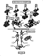
25310
25312 Assy.
25315
29220
29220
29220
25311
25314
25317 Assy.
25320
25361
25361
253324
219047M10x12
221420
M16x50
221420
M16x50
221420
M16x50
221420
M16x50
PAGE 72
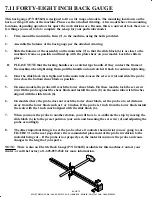
7.11 FORTY-EIGHT INCH BACK GAUGE
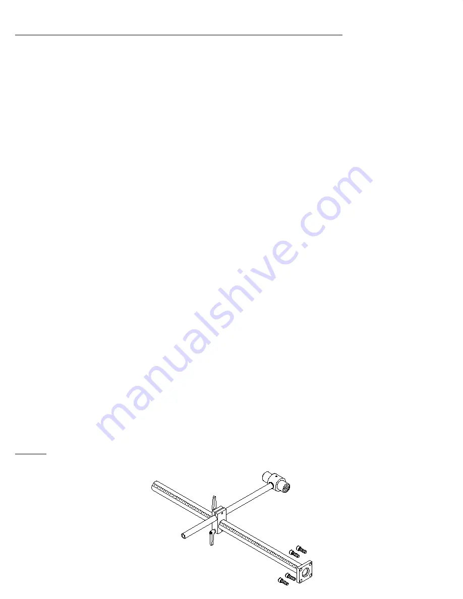
This back gauge (P/N 025603) is designed to fit a wide range of models. The mounting location is on the
back, or drop off side, of the machine. Please see the attached drawing. A few models have two mounting
locations, depending upon how far apart the work stations are. Because this is a universal tool, there are a
few things you need to do to complete the set-up for your particular model.
1.
First, mount the main tube, Item (7), to the machine, using the bolts provided.
2.
Assemble the balance of the back gauge per the attached drawing.
3.
Slide the balance of the assembly on the main tube (7) so that the slide block (6) is as close to the
machine's frame as possible and lined up with the plate shear on your model. Lock the slide in
place.
►
PLEASE NOTE that the locking handles are a ratchet type handle. If they contact the frame of
the machine when tightening them, pull the handle out and ratchet it back to continue tightening.
4.
Once the slide block (6) is tightened to the main tube, loosen the set screw (4) and slide the probe
in as close the bottom shear blade as possible.
5.
On some models, the probe will reach the lower shear blade. On these models, lock the set screw
(4) with the probe against the shear blade and install the scale (8) on the main tube with 0 inches
aligned with the slide block (6).
6.
On models where the probe does not reach the lower shear blade, set the probe at a set distance
away from the lower blade such as 1 or 2 inches. If the probe is 1 inch from the lower blade install
the scale with the 1 inch mark aligned with the slide block (6).
7.
When you move the probe to another station, you will have to re-calibrate the stop by moving the
slide block (6) in to the preset point on your scale and loosening the set screw (4) and adjusting the
probe accordingly.
8.
The other important thing is to set the probe where it contacts the material you are going to cut.
FIGURE 31 on the next page shows the recommended placement of the probe in relation to the
material being cut. . If the probe is not properly set, the material can move the probe and cause
changes in the length of your parts.
NOTE: There is also an Electric Back Gauge (P/N 026610) available for this machine. Contact your
dealer, or call the factory at 1-605-859-2542 for more information.
SCOTCHMAN INDS. - 180 E US HWY 14 - PO BOX 850 - PHILIP, SD 57567 Call: 1-605-859-2542


